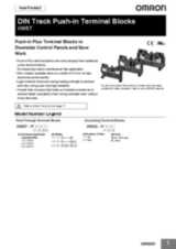
Контакты

(383)383-25-35
г. Новосибирск, мкр. Горский, 66, 2 этаж

XW5_-P


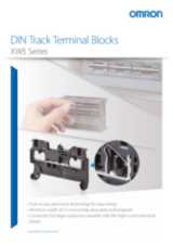
Блоки клемм Push-in для монтажа на DIN-рейку

Блоки безвинтовых клемм типа «Push-In Plus» для уменьшения размеров шкафов управления и упрощения монтажа

  • Усилие вставки всего 8 Н сокращает время и трудоемкость подключения проводов
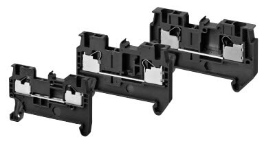
  • Клеммные блоки Push-in Plus более компактны по сравнению с обычными винтовыми клеммными блоками
  • Уменьшение размеров шкафов управления благодаря наличию моделей толщиной до 3,5 мм
  • Низкое усилие вставки и высокая сила удержания — простое подключение проводов и высокая надежность контакта
  • Отсутствует проблема ослабления затяжки винтов — нет необходимости в обслуживании

Ordering information

Classification

Product type

Nominal cross section
(mm²)

Number of levels

Number of cramp position per level

Color

Insulating material

Flammability rating
according to UL94

Pack
(pcs.)

Weight
(gram)

Order code

Feed Through Terminal blocks

Standard terminals

1.0

1

2

Dark grey

PA

V0

50

3.3

XW5T-P1.5-1.1-1

2.5

1

2

PA

V0

50

6.3

XW5T-P2.5-1.1-1

4

1

2

PA

V0

50

8.4

XW5T-P4.0-1.1-1

1.0

1

2

Blue

PA

V0

50

3.3

XW5T-P1.5-1.1-1BL

2.5

1

2

PA

V0

50

6.3

XW5T-P2.5-1.1-1BL

4

1

2

PA

V0

50

8.4

XW5T-P4.0-1.1-1BL

Multi tiers terminal

1.0

2

2

Dark grey

PA

V0

50

6.5

XW5T-P1.5-1.1-2

1.0

2

2

Blue

PA

V0

50

6.5

XW5T-P1.5-1.1-2BL

Multi conductor terminals

1.0

1

3

Dark grey

PA

V0

50

4.1

XW5T-P1.5-1.2-1

1.0

1

3

Blue

PA

V0

50

4.1

XW5T-P1.5-1.2-1BL

1.0

1

4

Dark grey

PA

V0

50

4.9

XW5T-P1.5-2.2-1

1.0

1

4

Blue

PA

V0

50

4.9

XW5T-P1.5-2.2-1BL

Grounding Terminal blocks

Standard terminals

1.0

1

2

Green/yellow

PA

V0

50

4.7

XW5G-P1.5-1.1-1

2.5

1

2

PA

V0

50

9.9

XW5G-P2.5-1.1-1

4

1

2

PA

V0

50

11.8

XW5G-P4.0-1.1-1

Multi tiers terminal

1.0

2

2

PA

V0

50

8.1

XW5G-P1.5-1.1-2

Multi conductor terminals

1.0

1

3

PA

V0

50

5.5

XW5G-P1.5-1.2-1

1.0

1

4

PA

V0

50

6.3

XW5G-P1.5-2.2-1

Accessories

Short bars

Applicable terminal blocks

No. of poles

Colors

Order code

XW5T-P1.5-_ or XW5G-P1.5-_

2

Red (RD)
Blue(BL)
Yellow (YL)

XW5S-P1.5-2__

3

XW5S-P1.5-3__

4

XW5S-P1.5-4__

5

XW5S-P1.5-5__

10

XW5S-P1.5-10__

XW5T-P2.5-_ or XW5G-P2.5-_

2

Red (RD)
Blue(BL)
Yellow (YL)

XW5S-P2.5-2__

3

XW5S-P2.5-3__

4

XW5S-P2.5-4__

5

XW5S-P2.5-5__

10

XW5S-P2.5-10__

XW5T-P4.0-_ or XW5G-P4.0-_

2

Red (RD)
Blue(BL)
Yellow (YL)

XW5S-P4.0-2__

3

XW5S-P4.0-3__

4

XW5S-P4.0-4__

5

XW5S-P4.0-5__

10

XW5S-P4.0-10__

Labels

Applicable terminal blocks

Description

Order code

XW5T-P1.5-_

For Top

1 sheet (102 pieces)

XW5Z-P1.5LB1

For Side

1 sheet (108 pieces)

XW5Z-P1.5LB2

XW5T-P2.5-_

For Top

1 sheet (72 pieces)

XW5Z-P2.5LB1

For Side

1 sheet (72 pieces)

XW5Z-P2.5LB2

XW5T-P4.0-_

For Top

1 sheet (60 pieces)

XW5Z-P4.0LB1

For Side

1 sheet (60 pieces)

XW5Z-P4.0LB2

End cover

Applicable terminal blocks

Order code

XW5_-P1.5-1.1-1

XW5E-P1.5-1.1-1

XW5_-P1.5-1.1-2

XW5E-P1.5-1.1-2

XW5_-P1.5-1.2-1

XW5E-P1.5-1.2-1

XW5_-P1.5-2.2-1

XW5E-P1.5-2.2-1

XW5_-P2.5-1.1-1

XW5E-P2.5-1.1-1

XW5_-P4.0-1.1-1

XW5E-P4.0-1.1-1

End brackets/Separator plates

Name

Width (mm)

Order code

End Brackets

6

XW5Z-EP6

Separator Plates

12

XW5Z-EP12

Specifications

Feed through terminal blocks

Model

XW5T-P1.5-1.1-1 (BL)

XW5T-P2.5-1.1-1 (BL)

XW5T-P4.0-1.1-1 (BL)

Appearance


Internal wiring

1 tier, 1:1

1 tier, 1:1

1 tier, 1:1

Applicable wire sizes

Nominal cross section

1.0 mm²

2.5 mm²

4 mm²

Minimum conductor cross section solid

0.14 mm²

0.14 mm²

0.2 mm²

Maximum conductor cross section solid

1.5 mm²

4.0 mm²

6.0 mm²

Minimum conductor cross section fine stranded

0.08 mm²

0.14 mm²

0.2 mm²

Maximum conductor cross section fine stranded

1.5 mm²

2.5 mm²

4.0 mm²

Minimum conductor cross section (flex., stranded) with ferrule with Plastic sleeve

0.14 mm²

0.14 mm²

0.2 mm²

Maximum conductor cross section (flex., stranded) with ferrule with Plastic sleeve

1.0 mm²

2.5 mm²

4.0 mm²

Conductor cross section AWG

AWG28 to AWG14

AWG26 to AWG12

AWG24 to AWG10

Wire strip length

8 mm

10 mm

12 mm

Dimensions (mm)

3.5×45×30.5

5.2×48.8×35.25

6.2×56.1×35.25

Mounting rail

TH35

TH35

TH35

IEC rated voltage

500 V

800 V

800 V

IEC rated current

13.5 A (17.5 A1)

24 A

32 A

Usage Group (UG)

B, C

D

B, C

UL rated voltage

300 V

51-150 V

151-300 V

301-600 V

600 V

UL rated current

15 A (SOL)

10 A (STR)

15 A (SOL)

10 A (STR)

10 A

5 A

20 A/AWG12 (SOL), 15 A/AWG14 (STR)

30 A/AWG10 (SOL), 20 A/AWG12 (STR)

Rated impulse voltage

6 kV

8 kV

8 kV

Dielectric strength

1,890 VAC for 60 min
(leakage current: 1 mA max.)

2,000 VAC for 60 min
(leakage current: 1 mA max.)

2,000 VAC for 60 min
(leakage current: 1 mA max.)

End cover

XW5E-P1.5-1.1-1

XW5E-P2.5-1.1-1

XW5E-P4.0-1.1-1

Special tool

XW4Z-00B

XW4Z-00B

XW4Z-00B

Applicable nameplates

XW5Z-P1.5LB_ or commercially available nameplate with 9.5 mm width and 0.5 mm thickness

XW5Z-P2.5LB_ or commercially available nameplate with 9.5 mm width and 0.5 mm thickness

XW5Z-P4.0LB_ or commercially available nameplate with 9.5 mm width and 0.5 mm thickness

Applicable Short bars

XW5S-P1.5-_
(_: Poles = 2, 3, 4, 5 or 10)

XW5S-P2.5-_
(_: Poles = 2, 3, 4, 5 or 10)

XW5S-P4.0-_
(_: Poles = 2, 3, 4, 5 or 10)


Model

XW5T-P1.5-1.1-2 (BL)

XW5T-P1.5-1.2-1 (BL)

XW5T-P1.5-2.2-1 (BL)

Appearance


Internal wiring

2 tiers, 1:1

1 tier, 1:2

1 tier, 2:2

Applicable wire sizes

Nominal cross section

1.0 mm²

1.0 mm²

1.0 mm²

Minimum conductor cross section solid

0.14 mm²

0.14 mm²

0.14 mm²

Maximum conductor cross section solid

1.5 mm²

1.5 mm²

1.5 mm²

Minimum conductor cross section fine stranded

0.08 mm²

0.08 mm²

0.08 mm²

Maximum conductor cross section fine stranded

1.5 mm²

1.5 mm²

1.5 mm²

Minimum conductor cross section (flex., stranded) with ferrule with Plastic sleeve

0.14 mm²

0.14 mm²

0.14 mm²

Maximum conductor cross section (flex., stranded) with ferrule with Plastic sleeve

1.0 mm²

1.0 mm²

1.0 mm²

Conductor cross section AWG

AWG28 to AWG14

AWG28 to AWG14

AWG28 to AWG14

Wire strip length

8 mm

8 mm

8 mm

Dimensions

3.5×65.7×41.1

3.5×54.1×30.5

3.5×63.2×30.5

Mounting rail

TH35

TH35

TH35

IEC rated voltage

500 V

500 V

500 V

IEC rated current

13.5 A (17.5 A2)

13.5 A (17.5 A1)

13.5 A (17.5 A1)

Usage Group (UG)

B, C

D

UL rated voltage

300 V

51-150 V

151-300 V

301-600 V

UL rated current

15 A (SOL), 10 A (STR)

15 A (SOL), 10 A (STR)

10 A

5 A

Rated impulse voltage

6 kV

6 kV

6 kV

Dielectric strength

1,890 VAC for 60 min
(leakage current: 1 mA max.)

1,890 VAC for 60 min
(leakage current: 1 mA max.)

1,890 VAC for 60 min
(leakage current: 1 mA max.)

End cover

XW5E-P1.5-1.1-2

XW5E-P1.5-1.2-1

XW5E-P1.5-2.2-1

Special tool

XW4Z-00B

XW4Z-00B

XW4Z-00B

Applicable nameplates

XW5Z-P1.5LB_ or commercially available nameplate with 9.5 mm width and 0.5 mm thickness

XW5Z-P1.5LB_ or commercially available nameplate with 9.5 mm width and 0.5 mm thickness

XW5Z-P1.5LB_ or commercially available nameplate with 9.5 mm width and 0.5 mm thickness

Applicable Short bars

XW5S-P1.5-_
(_: Poles = 2, 3, 4, 5 or 10)

XW5S-P1.5-_
(_: Poles = 2, 3, 4, 5 or 10)

XW5S-P1.5-_
(_: Poles = 2, 3, 4, 5 or 10)

Grounding terminal blocks

Model

XW5G-P1.5-1.1-1

XW5G-P2.5-1.1-1

XW5G-P4.0-1.1-1

Appearance


Internal wiring

1 tier, 1:1

1 tier, 1:1

1 tier, 1:1

Applicable wire sizes

Nominal cross section

1.0 mm²

2.5 mm²

4 mm²

Minimum conductor cross section solid

0.14 mm²

0.14 mm²

0.2 mm²

Maximum conductor cross section solid

1.5 mm²

4.0 mm²

6.0 mm²

Minimum conductor cross section fine stranded

0.08 mm²

0.14 mm²

0.2 mm²

Maximum conductor cross section fine stranded

1.5 mm²

2.5 mm²

4.0 mm²

Minimum conductor cross section (flex., stranded) with ferrule with Plastic sleeve

0.14 mm²

0.14 mm²

0.2 mm²

Maximum conductor cross section (flex., stranded) with ferrule with Plastic sleeve

1.0 mm²

2.5 mm²

4.0 mm²

Conductor cross section AWG

AWG28 to AWG14

AWG26 to AWG12

AWG24 to AWG10

Wire strip length

8 mm

10 mm

12 mm

Dimensions

3.5×45×30.5

5.2×48.8×35.25

6.2×56.1×35.25

Mounting rail

TH35

TH35

TH35

IEC rated voltage

500 V

800 V

800 V

IEC rated current

-

-

-

UL rated voltage

600 V

600 V

600 V

UL rated current

-

-

-

Rated impulse voltage

6 kV

8 kV

8 kV

Dielectric strength

1,890 VAC for 60 min
(leakage current: 1 mA max.)

2,000 VAC for 60 min
(leakage current: 1 mA max.)

2,000 VAC for 60 min
(leakage current: 1 mA max.)

End cover

XW5E-P1.5-1.1-1

XW5E-P2.5-1.1-1

XW5E-P4.0-1.1-1

Special tool

XW4Z-00B

XW4Z-00B

XW4Z-00B

Applicable nameplates

XW5Z-P1.5LB_ or commercially available nameplate with 9.5 mm width and 0.5 mm thickness

XW5Z-P2.5LB_ or commercially available nameplate with 9.5 mm width and 0.5 mm thickness

XW5Z-P4.0LB_ or commercially available nameplate with 9.5 mm width and 0.5 mm thickness

Applicable Short bars

XW5S-P1.5-_
(_: Poles = 2, 3, 4, 5 or 10)

XW5S-P2.5-_
(_: Poles = 2, 3, 4, 5 or 10)

XW5S-P4.0-_
(_: Poles = 2, 3, 4, 5 or 10)


Model

XW5G-P1.5-1.1-2

XW5G-P1.5-1.2-1

XW5G-P1.5-2.2-1

Appearance and internal wiring


Internal wiring

2 tiers, 1:1

1 tier, 1:2

1 tier, 2:2

Applicable wire sizes

Nominal cross section

1.0 mm²

1.0 mm²

1.0 mm²

Minimum conductor cross section solid

0.14 mm²

0.14 mm²

0.14 mm²

Maximum conductor cross section solid

1.5 mm²

1.5 mm²

1.5 mm²

Minimum conductor cross section fine stranded

0.08 mm²

0.08 mm²

0.08 mm²

Maximum conductor cross section fine stranded

1.5 mm²

1.5 mm²

1.5 mm²

Minimum conductor cross section (flex., stranded) with ferrule with Plastic sleeve

0.14 mm²

0.14 mm²

0.14 mm²

Maximum conductor cross section (flex., stranded) with ferrule with Plastic sleeve

1.0 mm²

1.0 mm²

1.0 mm²

Conductor cross section AWG

AWG28 to AWG14

AWG28 to AWG14

AWG28 to AWG14

Wire strip length

8 mm

8 mm

8 mm

Dimensions

3.5×65.7×41.1

3.5×54.1×30.5

3.5×63.2×30.5

Mounting rail

TH35

TH35

TH35

IEC rated voltage

500 V

500 V

500 V

IEC rated current

-

-

-

UL rated voltage

600 V

600 V

600 V

UL rated current

-

-

-

Rated impulse voltage

6 kV

6 kV

6 kV

Dielectric strength

1,890 VAC for 60 min
(leakage current: 1 mA max.)

1,890 VAC for 60 min
(leakage current: 1 mA max.)

1,890 VAC for 60 min
(leakage current: 1 mA max.)

End cover

XW5E-P1.5-1.1-2

XW5E-P1.5-1.2-1

XW5E-P1.5-2.2-1

Special tool

XW4Z-00B

XW4Z-00B

XW4Z-00B

Applicable nameplates

XW5Z-P1.5LB_ or commercially available nameplate with 9.5 mm width and 0.5 mm thickness

XW5Z-P1.5LB_ or commercially available nameplate with 9.5 mm width and 0.5 mm thickness

XW5Z-P1.5LB_ or commercially available nameplate with 9.5 mm width and 0.5 mm thickness

Applicable Short bars

XW5S-P1.5-_
(_: Poles = 2, 3, 4, 5 or 10)

XW5S-P1.5-_
(_: Poles = 2, 3, 4, 5 or 10)

XW5S-P1.5-_
(_: Poles = 2, 3, 4, 5 or 10)

Short bars

Model

XW5S-P1.5-_

XW5S-P2.5-_

XW5S-P4.0-_

Rated voltage

500 V

800 V

Rated current

17.5 A

24 A

32 A


1. Rated current with 1.5 mm² conductor cross section wire.

2. Rated current with 1.5 mm² conductor cross section wire.

1. Rated current with 1.5 mm² conductor cross section wire.

2. Rated current with 1.5 mm² conductor cross section wire.