| Item | Load power supply voltage range |
| 100 to 240 VAC | 400 to 480 VAC |
Power supply voltage | 100 to 240 VAC (50/60 Hz) |
Operating voltage range | 85 to 264 VAC |
Power consumption | 16 VA max. |
Load power supply voltage | 100 to 240 VAC | 400 to 480 VAC |
Load power supply voltage range | 75 to 264 VAC | 340 to 528 VAC |
Manipulated variable input | 0.0 to 100.0% (via RS-485 communications) |
Current transformer input | Single-phase AC, 0 to 50 A (primary current of CT) |
Trigger output | One voltage output for each channel, 12 VDC ±15%, max. load current: 21 mA
(with built-in short-circuit protection circuit) |
Alarm output | NPN open collector, one output
Max. applicable voltage: 30 VDC
Max. load current: 50 mA
Residual voltage: 1.5 V max.
Leakage current: 0.4 mA max. |
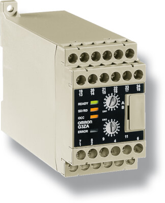
Indications | LED indicators |
Ambient operating temperature | -10 to 55°C (with no icing or condensation) |
Ambient operating humidity | 25 to 85% |
Storage temperature | -25 to 65°C (with no icing or condensation) |
| Performance |
Current indication accuracy | ±3 A (for models with heater burnout detection) |
Insulation resistance | 100 MΩ min. (at 500 VDC) between primary and secondary |
Dielectric strength | 2,000 VAC, 50/60 Hz for 1 min between primary and secondary |
Vibration resistance | Vibration frequency: 10 to 55 Hz, acceleration: 50 m/s 2 in X, Y, and Z directions |
Shock resistance | 300 m/s 2 three times each in six directions along three axes |
Weight | Approx. 200 g (including terminal cover) |
Degree of protection | IP20 |
Memory protection | EEPROM (non-volatile memory) (number of writes: 100,000) |
Installation environment | Overvoltage category III, pollution degree 2 (according to IEC 60664-1) |
Approved standards | UL508 (Listing), CSA22.2 No. 14
EN50178
EN61000-6-4 (EN55011: 1998, A1: 1999 Class A, Group 1)
EN61000-6-2: 2001 |
Size in mm (H×W×D) | 76×45×111 |