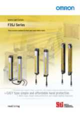
Контакты

(383)383-25-35
г. Новосибирск, мкр. Горский, 66, 2 этаж

F3SJ-E


Недорогая и удобная модель для простой защиты кистей рук

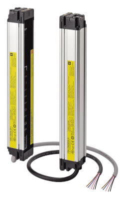
Семейство F3SJ-E — это световые барьеры безопасности типа 4 с разрешающей способностью 25 мм. Ширина барьера достигает 7 м, высота варьируется в пределах от 185 до 1105 мм, мертвая зона отсутствует.

  • Высота барьера = длина датчика
  • Компактный корпус
  • Простая защита кистей рук по доступной цене
  • Меньшее время монтажа благодаря меньшему количеству проводных соединений, наличию кронштейнов для быстрого монтажа и удобной центровке с помощью световых лучей
  • Датчик типа 4 в соответствии со стандартом EN 61496-1, уровень эффективности (PL) вплоть до «e» согласно EN ISO 13849

Ordering information

Application

Detection capability

Beam gap

Operating range

Protective height (mm)

Order code

Hand protection

Dia. 25 mm

20 mm

0.2 to 7 m

185 to 1,105

F3SJ-E ____ P25

Note: F3SJ-E uses a 3 m prewired discrete cable.


Number of beams

Protective height (mm)1

Order code

8

185

F3SJ-E0185P25

10

225

F3SJ-E0225P25

14

305

F3SJ-E0305P25

18

385

F3SJ-E0385P25

22

465

F3SJ-E0465P25

26

545

F3SJ-E0545P25

30

625

F3SJ-E0625P25

34

705

F3SJ-E0705P25

38

785

F3SJ-E0785P25

42

865

F3SJ-E0865P25

46

945

F3SJ-E0945P25

50

1,025

F3SJ-E1025P25

54

1,105

F3SJ-E1105P25

Accessories (sold separately)

Sensor mounting bracket

Appearance

Specifications

Application

Remarks

Order code


Top/bottom bracket

Top/bottom bracket for F3SJ-E/B

2 for an emitter,

2 for a receiver,

total of 4 per set

F39-LJB1


Intermediate bracket

In combination use with top/bottom bracket
for F3SJ-E/B

Can be used as free-location bracket.

1 set with 2 pieces

F39-LJB22 3


Quick mount bracket

Quick mount bracket for F3SJ-E/B

Supports M6 slide nut for aluminum frame.

1 set with 2 pieces

F39-LJB3-M61

Quick mount bracket for F3SJ-E/B

Supports M8 slide nut for aluminum frame.

F39-LJB3-M82


Quick mount M6 bracket

Quick mount M8 bracket

Bracket to mount an intermediate bracket to the aluminum frame
with a single touch.

Hexagon socket head cap screws
(M6 × 10) are included.

F39-LJB3-M6K1

Hexagon socket head cap screws
(M8 × 14) are included.

F39-LJB3-M8K2


Compatible mounting bracket

Mounting bracket used when replacing existing area sensors
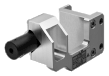
(F3SJ-A or F3SN) with the F3SJ-E/B.

2 for an emitter,

2 for a receiver,

total of 4 per set

F39-LJB4


Contact mount bracket

Bracket to closely contact the back side of the sensor.

2 for an emitter,

2 for a receiver,

total of 4 per set

F39-LJB5

Laser pointer

Appearance

Output

Order code


Laser pointer for F3SJ

F39-PTJ

Specifications

Model

F3SJ-E ____ P25

Sensor type

Type 4 safety light curtain

Setting tool connection4

Parameter settings: Not available

Safety category

Safety purpose of category 4, 3, 2, 1, or B

Detection capability

Opaque objects 25 mm in diameter

Beam gap (P)

20 mm

Number of beams (n)

8 to 54

Protective height (PH)

185 to 1,105 mm

Lens diameter

Diameter 5 mm

Operating range5

0.2 to 7 m

Response time (under stable light incident condition)

ON to OFF

15 ms max.

OFF to ON

70 ms max.

Startup waiting time

2 s max.

Power supply voltage (Vs)

SELV/PELV 24 VDC±20% (ripple p-p 10% max.)

Consumption current (no load)

Emitter: Up to 22 beams: 41 mA max., 26 to 42 beams: 57 mA max., 46 to 54 beams: 63 mA max.

Receiver: Up to 22 beams: 42 mA max., 26 to 42 beams: 47 mA max., 46 to 54 beams: 51 mA max.

Light source (emitted wavelength)

Infrared LED (870 nm)

Effective aperture angle (EAA)

Based on IEC 61496-2. Within ±2.5° for both emitter and receiver when the detection distance is 3 m or over

Safety outputs (OSSD)

Two PNP transistor outputs, load current 200 mA max., residual voltage 2 V max. (except for voltage drop due to cable extension), Leakage current 1 mA max., load inductance 2.2 H max.6, Maximum capacity load 1 μF7

Output operation mode

Safety output: On when receiving light

Input voltage

ON voltage: Vs-3 V to Vs, OFF voltage: 0 V to 1/2 Vs or open8

Mutual interference prevention function

Mutual interference prevention algorithm prevents interference in up to 3 sets.

Test function

Self test (at power-ON and at power distribution)

External test (emission stop function by test input)

Protection circuit

Output short-circuit protection, and power supply reverse polarity protection

Ambient temperature

Operating: -10 to 55°C (non-freezing), Storage: -25 to 70°C

Ambient humidity

Operating: 35% to 85% (no condensation), Storage: 35% to 95% RH

Operating ambient light intensity

Incandescent lamp: 3,000 lx max., Sunlight: 10,000 lx max.

Insulation resistance

20 MΩ min. (at 500 VDC)

Dielectric strength

1,000 VAC 50/60 Hz, 1 min

Degree of protection

IP65 (IEC 60529)

Vibration resistance

Malfunction: 10 to 55 Hz, Multiple amplitude of 0.7 mm, 20 sweeps in X, Y, and Z directions

Shock resistance

Malfunction: 100 m/s 2 , 1,000 times each in X, Y, and Z directions

Pollution degree

Pollution degree 3 (IEC 60664-1)

Power cable

Connection method: Pull-out type, cable length 3 m

Number of wires: Emitter: 5 wires, receiver: 6 wires

Cable diameter: Dia. 6 mm

Allowable bending radius: R5 mm

Extension cable

30 m max.9

Material

Case: Aluminum

Cap: ABS resin, PBT

Optical cover: PMMA resin (acrylic)

Cable: Oil resistant PVC

Weight (packed state)

Weight (g) = (protective height) × 2.6 + 800

Accessories

Test rod, Instruction Manual, User's Manual (CD-ROM)10

Applicable standards

IEC 61496-1, EN 61496-1 UL 61496-1, Type 4 ESPE (Electro-Sensitive Protective Equipment)

IEC 61496-2, CLC/TS 61496-2, UL 61496-2, Type 4 AOPD (Active Opto-electronic Protective Devices)

IEC 61508-1 to -3, EN 61508-1 to -3 SIL3
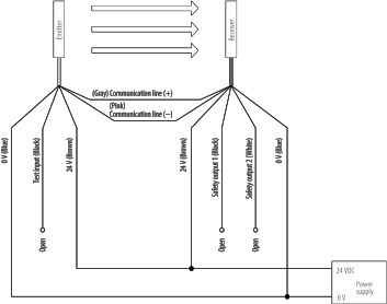
IEC 13849-1: 2006, EN ISO 13849-1: 2008 (PLe, Cat.4)

UL 508, UL 1998, CAN/CSA C22.2 No.14, CAN/CSA C22.2 No.0.8

Connections

Basic wiring diagram


1. Protective height (mm) = Total sensor length

2. Combining F39-LJB2 and F39-LJB3-M6K makes F39-LJB3-M6.

3. Combining F39-LJB2 and F39-LJB3-M8K makes F39-LJB3-M8.

4. Do not use the support software and setting console for F3SJ-A. Operation cannot be guaranteed.

5. Use of the spatter protection cover causes a 10% maximum sensing distance attenuation.

6. The load inductance is the maximum value when the safety output frequently repeats ON and OFF. When you use the safety output at 4 Hz or less, the usable load inductance becomes larger.

7. These values must be taken into consideration when connecting elements including a capacitive load such as capacitor.

8. The Vs indicates a voltage value in your environment.

9. To extend a cable of the F3SJ-E, refer to the user's manual (SCHG-733/732).

10. Mounting brackets are sold separately.