F3S-TGR-CL_A-K_/_B-K_
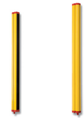
Световой барьер безопасности категории 4 / 2
Семейство датчиков безопасности F3S-TGR-CL_-K_ отличается простотой в подключении проводами, установке и конфигурированию, так как все модели для защиты пальцев, рук и частей тела типа 2 и типа 4 основаны на одинаковых принципах и предлагают одинаковый набор функций для выбора.
- 2-, 3 и 4 лучевые датчики безопасности
- Макс.. рабочая зона 12 в активном/пассивном режиме
- Макс.. рабочая зона 50 в активном/активном режиме
- Тип 2 или тип 4 в соответствии с EN61496-1
- Особенностями всех моделей являются: наружный контроль устройств, функции блокировки/
- запуска/повторного запуска и оптические мультиплексные каналы
- Усовершенствованные модели имеют функции селективного пропуска объектов и заданного сброса (выбор производится при помощи встроенных DIP-переключателей)
- Встроенная лампа селективного пропуска объектов
- Соответствие стандарту EN ISO 13849-1
Ordering information
Multi-beam safety sensors
F3S-TGR-CL2_-K_ (Type 2)
| Basic feature set1 | Advanced feature set2 | |||
|---|---|---|---|---|
F3S-TGR-CL4_-K_ (Type 4)
| Basic feature set1 | Advanced feature set2 | |||
|---|---|---|---|---|
Safety sensors
F3S-TGR-CL2_ (Type 2)
| Basic1 | 150 mm to 2,400 mm3 | ||||
| Advanced2 | |||||
| 150 mm to 2,250 mm3 | |||||
F3S-TGR-CL4_ (Type 4)
| Basic3 | 150 mm to 2,400 mm3 | ||||
| Advanced4 | |||||
| Master4 | 150 mm to 2,250 mm5 | ||||
| Slave6 | |||||
F3S-TGR-CL-_-_M/S Master-Slave Series
- A Master-Slave cascade system is made of one master segment and one slave segment.
- The length of the total protective field can vary from minimum 300 mm till maximum 2,400 mm.
- The interconnect cable length limitation between master and slave segment is in total max. 0,9 m.
Possible combinations of master and slave are in this table:
Accessories
Receiver cables (M12-8pin, shielded, flying leads)
 | Sensor connector with open cable end M12-8pin, outer shielding layer | ||
Transmitter cables (M12-4pin, shielded, flying leads)
 | Sensor connector with open cable end M12-4pin, outer shielding layer | ||
Mounting brackets
 | F39-TGR-ST-SB7 | ||
 |
Master-Slave accessories
 | Male-male extension connector M12-8pin, outer shielding layer | ||
 |
Laser alignment kit
 |
Mounting systems and mirrors
Adjustable stands
Mirror system for multi-beam safety sensors (F3S-TGR-CL_-K_)
Muting accessories
Cable cover
Specifications
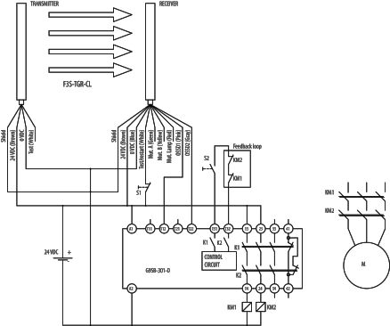
Multi-beam safety sensors
Finger- and hand safety protection sensors
F3S-TGR-CL and G9SB-301-D in manual reset
Брошюры
Показать все Брошюры
Каталоги
Показать все Каталоги
Спецификации
Показать все Спецификации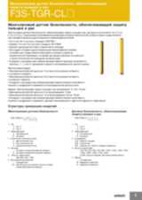
Технические руководства
Показать все Технические руководства
Программное обеспечение

SISTEMA Library Программное обеспечение
Пожалуйста, войдите или получите прямой доступ к скачиванию данного документа