Контакты

(383)383-25-35
г. Новосибирск, мкр. Горский, 66, 2 этаж

G7SA


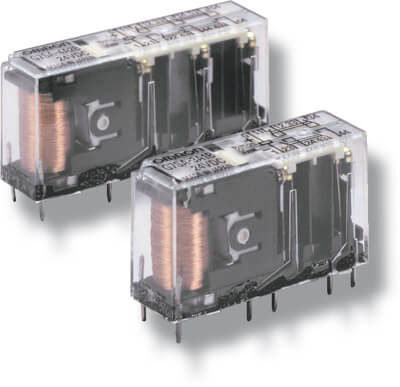
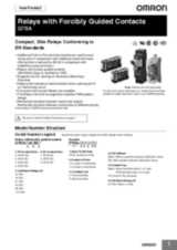
Реле с механически связанными контактами

Семейство миниатюрных реле G7SA с механически связанными контактами объединяет 4-полюсные и 6-полюсные модели с различными комбинациями контактов и усиленной изоляцией. Специальное расположение выводов упрощает монтаж на печатную плату. Реле G7SA допускают монтаж пайкой или установку в монтажные колодки P7SA.

  • Механически связанные контакты.
  • Соответствие EN 50205.
  • 6 A при 240 В~ и 6 A при 24 В= для резистивной нагрузки.
  • Усиленная изоляция между входами, выходами и полюсами.
  • 4-полюсные и 6-полюсные модели.
  • Доступны монтажные колодки с безвинтовыми клеммами «Push-in»

Ordering information

Relays with forcibly guided contacts

Type

Sealing

Poles

Contacts

Rated voltage

Order code

Standard

Flux-tight

4 poles

3PST-NO, SPST-NC

24 VDC1

G7SA-3A1B

DPST-NO, DPST-NC

G7SA-2A2B

6 poles

5PST-NO, SPST-NC

G7SA-5A1B

4PST-NO, DPST-NC

G7SA-4A2B

3PST-NO, 3PST-NC

G7SA-3A3B

Sockets

Mounting

Terminal type

LED indicator

Poles

Coil rated voltage

Order code

Front-
mounting

Push-In Plus terminals

Yes

4 poles

24 VDC

P7SA-10F-ND-PU

6 poles

P7SA-14F-ND-PU

Screw terminals

Yes

4 poles

P7SA-10F-ND

6 poles

P7SA-14F-ND

No

4 poles

P7SA-10F

6 poles

P7SA-14F

Back-
mounting

PCB terminals

No

4 poles

P7SA-10P

6 poles

P7SA-14P

Specifications

Coil

Rated voltage

Rated current

Coil resistance

Must-operate voltage

Must-release voltage

Max. voltage

Power consumption

24 VDC

4 poles: 15 mA

6 poles: 20.8 mA

4 poles: 1,600 Ω
6 poles: 1,152 Ω

75% max. (V)

10% min. (V)

110% (V)

4 poles: Approx. 360 mW
6 poles: Approx. 500 mW

Note: Refer to datasheet for details

Contacts

Load

Resistive load (cos φ = 1)

Rated load

6 A at 250 VAC, 6 A at 30 VDC

Rated carry current

6 A

Max. switching voltage

250 VAC, 125 VDC

Max. switching current

6 A

Max. switching capacity (reference value)

1,500 VA, 180 W

Relays with forcibly guided contacts

Contact resistance

100 mΩ max. (The contact resistance was measured with 1 A at 5 VDC using the voltage-drop method.)

Operating time 2

20 ms max.

Response time 1

10 ms max.
(The response time is the time it takes for the normally open contacts to open after the coil voltage is turned OFF.)

Release time 1

20 ms max.

Insulation resistance

100 MΩ min. (at 500 VDC) (The insulation resistance was measured with a 500 VDC megger at the same places that the dielectric strength was
measured.)

Dielectric strength 3 4

Between coil contacts/different poles: 4,000 VAC, 50/60 Hz for 1 min
(2,500 VAC between poles 3-4 in 4-pole Relays or poles 3-5, 4-6, and 5-6 in 6-pole Relays.)

Between contacts of same polarity: 1,500 VAC, 50/60 Hz for 1 min

Durability

Mechanical

10,000,000 operations min. (at approx. 36,000 operations/hr)

Electrical

100,000 operations min. (at the rated load and approx. 1,800 operations/hr)

Min. permissible load5

5 VDC, 1 mA (reference value)

Ambient temperature 6

Operating: −40 to 85°C (with no icing or condensation)

Ambient humidity

Operating: 35 to 85%

Approved standards

EN61810-1 (IEC61810-1), EN50205, UL508, CSA22.2 No. 14

Note: The values listed above are initial values.


Please check Omron in the Internet for updated information on product reliability data and the SISTEMA libraries: http://industrial.omron.eu/safety


1. 12 VDC, 21 VDC, 48 VDC are available on request.
2. These times were measured at the rated voltage and an ambient temperature of 23°C. Contact bounce time is not included.
3. Pole 3 refers to terminals 31-32 or 33-34, pole 4 refers to terminals 43-44, pole 5 refers to terminals 53-54, and pole 6 refers to terminals 63-64.
4. When using a P7SA socket, the dielectric strength between coil contacts/different poles is 2,500 VAC, 50/60 Hz for 1 min.
5. Min. permissible load is for a switching frequency of 300 operations/min.
6. When operating at a temperature between 70°C and 85°C, reduce the rated carry current (6 A at 70°C or less) by 0.1 A for each degree above 70°C.