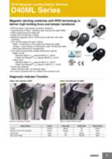
Контакты

(383)383-25-35
г. Новосибирск, мкр. Горский, 66, 2 этаж

D40ML


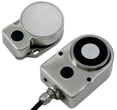
Магнитные блокирующие выключатели безопасности с RFID

Магнитный замок в сочетании с RFID обеспечивает высокую силу запирания и устойчивость к манипуляциям

  • RFID обеспечивает высокую степень защиты от манипуляций
  • Гигиеничный дизайн — исполнения из нержавеющей стали имеют степень защиты IP69K
  • Удобная диагностика неисправностей с помощью светодиодов
  • Последовательное соединение до 20 выключателей
  • Ответные части с общим и уникальным кодированием типа 4
  • Два размера выключателей с различными силами запирания
  • Три типа корпуса: пластиковый, литой металлический, из нержавеющей стали марки 316
  • Уровень безопасности до PLe (в соответствии с ISO 13849-1)

Ordering information

Switches

Case material

Holding force F1 max (typical)

Actuator type

Cable configuration

Order code

316 Stainless Steel (IP69K)

600 N

Unique

5 m Cable

D40ML-SS2-U-5M

10 m Cable

D40ML-SS2-U-10M

Pigtail w/ M12 Connector

D40ML-SS2-U-M12

Basic

5 m Cable

D40ML-SS2-B-5M

10 m Cable

D40ML-SS2-B-10M

Pigtail w/ M12 Connector

D40ML-SS2-B-M12

950 N

Unique

5 m Cable

D40ML-SS1-U-5M

10 m Cable

D40ML-SS1-U-10M

Pigtail w/ M12 Connector

D40ML-SS1-U-M12

Basic

5 m Cable

D40ML-SS1-B-5M

10 m Cable

D40ML-SS1-B-10M

Pigtail w/ M12 Connector

D40ML-SS1-B-M12

Plastic (IP67)

900 N

Unique

5 m Cable

D40ML-P2-U-5M

10 m Cable

D40ML-P2-U-10M

Pigtail w/ M12 Connector

D40ML-P2-U-M12

Basic

5 m Cable

D40ML-P2-B-5M

10 m Cable

D40ML-P2-B-10M

Pigtail w/ M12 Connector

D40ML-P2-B-M12

1500 N

Unique

5 m Cable

D40ML-P1-U-5M

10 m Cable

D40ML-P1-U-10M

Pigtail w/ M12 Connector

D40ML-P1-U-M12

Basic

5 m Cable

D40ML-P1-B-5M

10 m Cable

D40ML-P1-B-10M

Pigtail w/ M12 Connector

D40ML-P1-B-M12

Diecast Metal (IP67)

900 N

Unique

5 m Cable

D40ML-M2-U-5M

10 m Cable

D40ML-M2-U-M12

Pigtail w/ M12 Connector

D40ML-M2-U-M12

Basic

5 m Cable

D40ML-M2-B-5M

10 m Cable

D40ML-M2-B-10M

Pigtail w/ M12 Connector

D40ML-M2-B-M12

1500 N

Unique

5 m Cable

D40ML-M1-U-5M

10 m Cable

D40ML-M1-U-10M

Pigtail w/ M12 Connector

D40ML-M1-U-M12

Basic

5 m Cable

D40ML-M1-B-5M

10 m Cable

D40ML-M1-B-10M

Pigtail w/ M12 Connector

D40ML-M1-B-M12

Spare Actuators

Product Description

Order code

Stainless Steel; IP69K; 950 N; Basic Code; Actuator

D40ML-SS1-B-ACT

Stainless Steel; IP69K 600 N; Basic Code; Actuator

D40ML-SS2-B-ACT

Diecast Metal; IP67; 1500 N; Basic Code; Actuator

D40ML-M1-B-ACT

Diecast Metal; IP67; 900 N; Basic Code; Actuator

D40ML-M2-B-ACT

Plastic; IP67; 1500 N; Basic Code; Actuator

D40ML-P1-B-ACT

Plastic; IP67; 900 N; Basic Code; Actuator

D40ML-P2-B-ACT

Note: Spare actuators are not available for uniquely coded switches.

Accessories

Product Description

Order code

Quick Disconnect Cable, 8-pin M12 to Flying Leads, PVC Jacket, 5 Meter Length

D40ML-CBL-M12-5M

Quick Disconnect Cable, 8-pin M12 to Flying Leads, PVC Jacket, 10 Meter Length

D40ML-CBL-M12-10M

  • Note 1. The quick disconnect cable has an identical cable pining as the switch wiring.
  • 2. Y92E-M12PURSH8S M-L disconnect cables are also compatible with D40ML.


Specifications

Codes and Standards

IEC 60947-5-3:2013, EN 60947-5-1:2004 + AC:2005 + A1:2009,
EN 60947-1:2007 + A1:2011, EN ISO 13849-1:2008 + AC:2009,
EN 62061:2005 + AC:2010 + A1:2013, ISO 14119:2013, UL508

Safety Classification and Reliability Data

Minimum Switched Current

10 VDC 1 mA

Dielectric Withstand

250 VAC

Insulation Resistance

100 M Ω

Shock Resistance

11 ms 30G

Vibration Resistance

10 to 55 Hz, 1 mm amplitude

Switching Distance

S ao 1 mm Close; S ar 10 mm Open

Misalignment

Between switch and actuator, 2 mm in any direction

Switching Frequency

1.0 Hz maximum

Response Time (On –> Off)

10 ms max.

Operating Time (Off –> On)

150 ms

Approach Speed

200 to 1000 mm/s

Body Material

D40ML-P_: Plastic

D40ML-M_: Diecast Metal

D40ML-SS_: 316 Stainless Steel

Actuator Seal: Silicone

Encapsulation: High Temperature Epoxy

Operating Temperature Range

–25 to 40°C

Ambient Operating Humidity

up to 90% at 25 ~ 40°C

Enclosure Protection

IP67 (Plastic or Diecast Metal)

IP69K (Stainless steel versions with flying leads)

Cable Type

PVC 8 core, 6 mm outer diameter

Mounting Bolts

2 × M5 Tightening torque 1.0 Nm

Mounting Position

Any

Power Supply

24 VDC ±10% (selv / pelv)

Power Consumption

Unlocked: 50 mA max.

Locked:

  • Medium Duty 325 mA max.
  • Heavy Duty 500 mA max.

Holding Force

Medium Duty

  • Stainless Steel: F1 max (typical) 600 N, F zh 1 450 N
  • Plastic and Diecast: F1 max (typical) 900 N, F zh 675 N

Heavy Duty

  • Stainless Steel: F1 max (typical) 950 N, F zh 700 N
  • Plastic and Diecast: F1 max (typical) 1500 N, F zh 1150 N

Max. Switched Current (Outputs)

200 mA (min. internal resistance 8.5 Ohms)

Auxiliary Signal

+24 VDC (Door Open)

Characteristic Data according to EN ISO13849-1

PLe: If both channels are used in combination with a SIL3/PLe control device

Category: Cat. 4

MTTFd: 1100a

Diagnostic Coverage DC: 99% (high)

Number of operating days per year: d op = 365d

Number of operating hours per day: h op = 24h

B10d: Not mechanical parts implemented

Characteristic Data according to IEC62061
(used as a sub system)

Safety Integrity Level: SIL3

PFH (1/h): 4.77E-10 Corresponds to 4.8% of SIL3

PFD: 4.18E-05 Corresponds to 4.2% of SIL3

Proof Test Interval T 1 : 20a

Information with regard to UL508

Use LVLC or Class 2 supply. Type 1 enclosure.

Risk Time in accordance with EN 60947-5-3

150 ms (switching off delay at removal of actuator)

Note: When the product use deviates from these assumptions (different load, operating frequency, etc.) the values must be adjusted accordingly.


1. A new test has been introduced with the coefficient 1.3. A device with a specified maximum holding force (F zh ) of 500 N needs to hold up a force test (F1 max ) at 650 N.
According to the standard the locking force F zh should be stated for every guard locking switch.

1. A new test has been introduced with the coefficient 1.3. A device with a specified maximum holding force (F zh ) of 500 N needs to hold up a force test (F1 max ) at 650 N.
According to the standard the locking force F zh should be stated for every guard locking switch.