ZX-T

Микропроцессорный контактный измерительный датчик
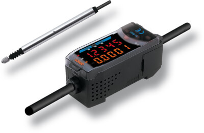
Датчик ZX-T идеально подходит для тех случаев, когда объект обнаружения может быть покрыт масляным нагаром или прочими загрязнениями микронных размеров. В таких случаях контактное измерение - наиболее надежный способ.
- Модульная концепция объединения различных технологий измерения в единую платформу
- Модели с воздушным втягиванием для автоматизированного контроля
- Подключение до восьми датчиков для многоканального измерения
- Сигнализация превышения силы нажатия предотвращает возникновение аварийных режимов
- Прочная шарикоподшипниковая конструкция обеспечивает длительный срок службы
Ordering information
Sensors
Sensor heads
Note: The resolution refers to the minimum value that can be read when a ZX-TDA_1 amplifier unit is connected.
Amplifier units
Accessories (order separately)
Calculating unit
ZX-series communications interface unit
SmartMonitor sensor setup tool for Personal Computer connection
| ZX-SW11EV31 |
Cables with connectors on both ends (for extension)*
* Robot cable models are also available. The model numbers are ZX-XC_R.
Preamplifier mounting brackets
Actuators
| Measuring ordinary flat surfaces (standard |  | ||||
 | |||||
 | |||||
 | |||||
 | |||||
| Mounting D5SN-TN1/-TF1 or commercially |  |
Note:  Replacement possible
  Conversion adapter required
Specifications
Amplifier units
| Possible average count settings3 | ||
| Linear output4 | Current output: 4 to 20 mA/F.S., max. load resistance: 300 Ω Voltage output: ±4 V (±5 V, 1 to 5 V5), output impedance: 100 Ω | |
| NPN open-collector outputs, 30 VDC, 30 mA max. | PNP open-collector outputs, 30 VDC, 30 mA max. | |
| Zero reset input, timing input, reset input, judgement output hold input | ON: Supply voltage short-circuited or supply voltage of 1.5 V or less | |
| ||
| Judgement indicators: High (orange), pass (green), low (yellow), 7-segment main digital display (red), 7-segment sub-digital | ||
| 140 mA max. (with sensor connected), for 24-VDC power supply voltage: 140 mA max. (with sensor connected) | ||
| Operating and storage: 0 to 50°C (with no icing or condensation) | ||
| Case: PBT (polybutylene terephthalate), cover: Polycarbonate | ||
Sensor heads
| Resolution7 | ||||
| Linearity8 | ||||
| Operating force 9 | ||||
| Operating: 0 to 50°C, storage: - 15 to 60°C (with no icing or condensation) | ||||
| Operating and storage: 35% to 85% (with no icing or condensation) | ||||
| Temperature characteristic10 | ||||
| Instruction manual, preamplifier mounting brackets (ZX-XBT1) | ||||
1. When using the ZX-TDA11/41 with the SmartMonitor, either the ZX-SFW11EV3 or the
ZX-SW11EV3 SmartMonitor must be used. Earlier versions cannot be used.
3. The response speed of the linear output is calculated as the measurement period x (average count setting + 1).
The response speed of the judgement outputs is calculated as the measurement period x (average count setting + 1).
4. The output can be switched between a current output and voltage output using a switch on the bottom of the amplifier unit.
7. The resolution is given as the minimum value that can be read when a ZX-TDA_1 amplifier unit is connected. This value is taken 15 minutes after turning ON the power with the average number of operations set to 256.
9. These figures are representative values that apply for the measurement mid-point, and are for when the provided actuator is used, with the actuator moving downwards. If the actuator moves horizontally or upwards, the operating force will be reduced. Also, if an actuator other than the standard one is used, the operating force will vary with the weight of the actuator itself.


