Xpectia FZ5/Lite
Простота, гибкость и кристальная ясность
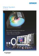
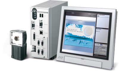
Новое устройство FZ5 сочетает преимущества интеллектуальной камеры и мощной системы технического зрения на одной платформе. Уникальная четкость изображения, достигаемая с помощью интеллектуальной камеры, позволяет упростить настройку, ускорить установку и повысить оптическую производительность.
- Идеально четкое изображение
- Система обеспечения натуральных цветов (16 миллионов цветов)
- C-образное крепление и интеллектуальные камеры
- Связь EtherNet/IP и TCP/IP
Flexible flow configuration
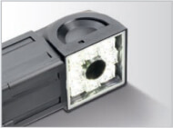
FZ5 поддерживает технологии интеллектуальных камер датчиков серии FQ. Это позволяет быстро и просто установить камеру на машину без дополнительной оптики и подсветки. Кристально четкие изображения легко захватываются с помощью высокомощного освещения и поляризационного фильтра, устраняющего блики.
Simple operation
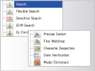
FZ5 включает в себя более 70 инструментов обработки, таких как инструменты измерения размеров, поиска по различным параметрам (узор, контур), дефектов, кромок и подсчета. Эти инструменты обработки можно объединить в потоковой программе с возможностью ответвлений и циклов. Это обеспечивает создание нового измерения гибкости для компактных датчиков технического зрения.
Open network
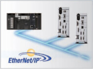
Поддерживается EtherNet/IP - глобальный стандарт для сетей данных автоматизации предприятий - в целях беспрепятственной интеграции в производственную линию или машину. Это позволяет пользователям подключать любые поддерживающие EtherNet/IP устройства любых производителей. Также возможна связь по протоколу TCP/IP, последовательному и параллельному интерфейсам.
System configuration
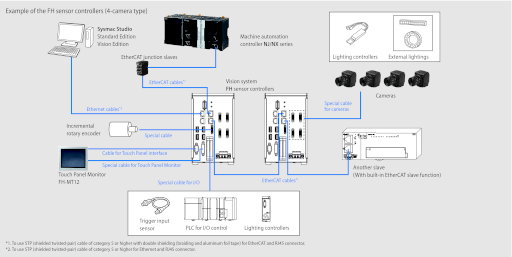
EtherCAT connections for FH series
Ordering information
FH series sensor controllers
 | |||||
FZ5 Lite series sensor controllers
 | |||||
Note: Refer to the FZ5 Series Data sheet (Cat. No. Q203) for Ratings, Specifications and Accessories.
Cameras
 | (Up to four cameras can be connected to one Controller. Up to eight cameras other than | 25.7 ms1 | |||
 | 8.5 ms1 | ||||
| 4.6 ms1 | |||||
 | |||||
 | (When connecting FZ5-L35_, up to two cameras can be connected.) | ||||
 | |||||
 | |||||
 | |||||
 | |||||
 | |||||
 | |||||
 | |||||
| 2 Cables2 | High Speed Mode3 | |||||||
| High Speed Mode2 | ||||||||
Camera Cables
| Order code4 | ||
|---|---|---|
 | Cable length: 2 m, 3 m, 5m, or 10 m5 | |
 | Cable length: 2 m, 3 m, 5m, or 10 m2 | |
 | Right-angle Camera Cable6 Cable length: 2 m, 3 m, 5m, or 10 m2 | |
 | Bend resistant Right-angle Camera Cable3 Cable length: 2 m, 3 m, 5 m, or 10 m2 | |
 | Cable length: 15 m2 | |
 | Long-distance Right-angle Camera Cable3 Cable length: 15 m2 | |
 | Up to two Extension Units and three Cables can be connected. (Maximum cable length: 45 m2) |
Cameras/Cables connection table
| High-speed CMOS cameras7 | |||||||||
|---|---|---|---|---|---|---|---|---|---|
| Long-distance camera cable Long-distance right-angle camera cable | |||||||||
| Long-distance camera cable Long-distance right-angle camera cable | ||||||||
Maximum extension length using Cable Extension Units FZ-VSJ
| Transmission speed8 | No. of CH used for connection9 | Maximum cable length | |||||
|---|---|---|---|---|---|---|---|
| 410 | |||||||
| 43 | |||||||
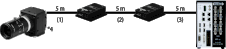
Connection configuration
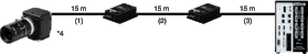
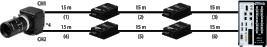
| Connection configuration using the maximum length of Camera Cables | ||
|---|---|---|
 | ||
 |  | |
 | ||
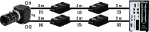 |  |
Note: Select the Camera Cables between the Controller and Extension Unit, between the Extension Units, and between the Extension Unit and Camera according to the connected Camera. Different types or lengths of Camera Cables can be used for (1), (2), and (3) as well as for (4), (5), and (6). However, the type and length of Camera Cable (1) must be the same as those of Camera Cable (4), (2) must be the same as (5), and (3) must be the same as (6).
Touch Panel Monitor
| Touch Panel Monitor 12.1 inches |

Touch Panel Monitor Cables
 | ||
 | XW2Z- ___ PP-112 | |
 |
A video signal cable and an operation signal cable are required to connect the Touch Panel Monitor.
Parallel I/O cables/Encoder cable
 | Parallel I/O Cable13 | XW2Z-S013-_14 |
 | Parallel I/O Cable for Connector-terminal Conversion Unit1 Cable length: 0.5 m, 1 m, 1.5 m, 2 m, 3 m, 5 | XW2Z- ___ EE15 |
 | Connector-Terminal Block Conversion Units, General-purpose devices | XW2R-_34G-T16 |
 |
Recommended EtherCAT and EtherNet/IP communications cables
Use Straight STP (shielded twisted-pair) cable of category 5 or higher with double shielding (braiding and aluminum foil tape) for EtherCAT.
Use Straight or cross STP (shielded twisted-pair) cable of category 5 or higher for EtherNet/IP.
 | Standard type cable with connectors on both ends (RJ45/RJ45) Wire gauge and number of pairs: AWG27, 4-pair cable, cable sheath material: LSZH17, Cable color: Blue, Yellow, or Green, Cables length: 0.2 m, 0.3 m, 0.5 m, 1 m, 1.5 m, 2 m, 3 m, 5 m, 7.5 m, 10 m, 15 m, 20 m | XS6W-6LSZH8SS_CM-Y18 | |||
 | Rugged type cable with connectors on both ends (RJ45/RJ45) | XS5W-T421-_MD-K2 | |||
 | Rugged type cable with connectors on both ends (M12/RJ45) | XS5W-T421-_MC-K2 | |||
 | Rugged type cable with connectors on both ends (M12 L/RJ45) | XS5W-T422-_MC-K2 | |||
- | SAB 0.5 × 4P19 | ||||
- | KETH-SB3 | ||||
- | FAE-50043 | ||||
- | MPS588-C3 | ||||
- | KETH-PSB-OMR20 | ||||
- | PNET/B 4 | ||||
 | XS6G-T421-14 | ||||
- | F-LINK-E 0.5mm × 4P21 | ||||
- | MPS588 5 | ||||
Note: Please be careful while cable processing, for EtherCAT, connectors on both ends should be shield connected and for EtherNet/IP, connectors on only one end should be shield connected.
Automation software Sysmac Studio
Please purchase a DVD and licenses the first time you purchase the Sysmac Studio. DVDs and licenses are available individually. The license does not include the DVD.
| The Sysmac Studio is the software that provides an integrated environment for setting, programming, debugging and maintenance of machine automation controllers including the NJ/NX Series, EtherCat Slave, and the HMI. Sysmac Studio runs on the following OS. Windows XP (Service Pack 3 or higher, 32-bit version)/ Windows Vista (32-bit version)/Windows 7 (32-bit/64-bit version)/Windows 8 (32-bit/64-bit version)/Windows 8.1 (32-bit/64-bit version) | DVD 22 | |||
| Sysmac Studio Vision Edition is a limited license that provides selected functions required for FH-series/FQ-M-series vision sensor settings. | ||||
Note: 1. Site licenses are available for users who will run Sysmac Studio on multiple computers. Ask your OMRON sales representative for details.
2. Sysmac Studio version 1.07 or higher supports the FH series. Sysmac Studio does not support the FZ5 series.
Development Environment
Please purchase a DVD and licenses the first time you purchase the Sysmac Studio. DVDs and licenses are available individually. The license does not include the DVD.
Accessories
 | For Box-type Controllers25 | ||||
 | Cable length: 2 m or 5 m (When you connect a LCD Monitor FZ-M08 to FH sensor controller, please use it in combination with a DVI-I -RGB Conversion Connector FH-VMRGB.) | ||||
 | |||||
 | |||||
 | |||||
 | |||||
| (A mouse that requires the mouse driver to be installed is not supported.) | |||||
 | |||||
 | |||||
 | |||||
 | |||||
| FLV Series26 | |||||
| FL Series2 | |||||
 | FLV-TCC Series2 | ||||
 | FLV-ATC Series2 | ||||
 | FL-TCC Series2 | ||||
 | |||||
 | |||||
 | |||||
Lenses
C-mount Lens for 1/3-inch image sensor (Recommend: FZ-S_/FZ-SH_/FH-S_)
 |  |  |  |  |  |  |  |  |  |  | |
C-mount Lens for 2/3-inch image sensor (Recommend: FZ-S_2M/FZ-S_5M2/FH-S_02)
(3Z4S-LE SV-7525H and 3Z4S-LE SV-10028H can also be used for FH-S_04)
 |  |  |  |  |  |  |  |  | |
C-mount Lens for 1-inch image sensor (Recommend: FH-S_02/FH-S_04)
(3Z4S-LE SV-7525H with focal length of 75 mm and 3Z4S-LE SV-10028H with focal length of 100 mm are also available.)
 |  |  |  |  |  |  | |
M42-mount Lens for large image sensor (Recommend: FH-S_12)
 |  |  |  |  |  | |
Lenses for small camera
 |  |  |  | |
Vibrations and Shocks Resistant C-mount Lens for 2/3-inch image sensor
(Recommend: FZ-S_/FZ-S_2M/FZ-S_5M2/FZ-SH_/FH-S_)
(Vibrations and Shocks Resistant Lenses for 1-inch image sensors and for large image sensors are also available. Ask your OMRON representative for details.)
| VS-MC15- _____ 1 | VS-MC20- _____ 1 | |||||||||||||||||
 |  | |||||||||||||||||
| (fixed F No.)2 | ||||||||||||||||||
| Depth of field (mm)3 | ||||||||||||||||||
| VS-MC25N- _____ 1 | VS-MC30 _____ 1 | |||||||||||||||||
 |  | |||||||||||||||||
| (fixed F No.)2 | ||||||||||||||||||
| Depth of field (mm)3 | ||||||||||||||||||
| VS-MC35- _____ 1 | VS-MC50- _____ 1 | |||||||||||||||||
 |  | |||||||||||||||||
| (fixed F No.)2 | ||||||||||||||||||
| Depth of field (mm)3 | ||||||||||||||||||
| VS-MC75- _____ 27 | |||||||||
 | |||||||||
| (fixed F No.)28 | |||||||||
| Depth of field (mm)29 | |||||||||
High-resolution Telecentric Lens for C-mount Lens for 2/3-inch image sensor (Recommend:FZ-S_/FZ-SH_/FZ-S_2M/FZ-S_5M2/FH-S_)
| Model30 | ||||||||||||
|---|---|---|---|---|---|---|---|---|---|---|---|---|
| WD (mm)31 | ||||||||||||
| Depth of field (mm)32 | ||||||||||||
| Resolution33 | ||||||||||||
- Note 1. Fixing the lens or other reinforcement may be required depending on the installation angle or operating environment (vibration/shock).
When fixing the lens, insulate the lens from the fixture. - 2. The above specifications are values calculated from the optical design and can vary depending on installation conditions.
Specifications
FH sensor controllers
| Can be connected to all cameras. (Can be connected to up to four 12 million-pixel cameras or up to eight cameras other than 12 million-pixel cameras.) | Can be connected to all cameras. (Can be connected to up to four 12 million-pixel cameras or up to eight cameras other than 12 million-pixel cameras.) | ||||||||
| Create series of processing steps by editing the flowchart (Help messages provided). | |||||||||
| Japanese, English, Chinese (simplified), Chinese (Traditional), Korean, German, French, Italian, Spanish | |||||||||
| Either an NPN or PNP output is supported (switchable). (In the 2-line random trigger mode) 17 inputs (STEP0/ENCTRIG_Z0, STEP1/ENCTRIG_Z1, ENCTRIG_A0 to 1, ENCTRIG_B0 to 1, DSA0 to 1, DI0 to 7, DI_LINE0) 37 outputs (RUN0 to 1, READY0 to 1, BUSY0 to 1, OR0 to 1, ERROR0 to 1, GATE0 to 1, STGOUT0/SHTOUT0, STGOUT1/SHTOUT1, STGOUT2 to 7, DO0 to 15, ACK) (In the 5-line to 8-line random trigger mode) 19 inputs, STEP0 to 7, DI_LINE0 to 2, DI0 to 7) 34 outputs (READY0 to 7, BUSY0 to 7, OR0 to 7, ACK, ERROR, STGOUT/SHTOUT0 to 7) | |||||||||
| RS422-A line driver level. Phase A/B: single-phase 4MHz (multiplying phase difference of 1MHz by 4 times), Phase Z: 1MHz | |||||||||
| DVI-I (analog RGB & DVI-D single link) output interface × 1 channel34 | |||||||||
| When connected to a 300,000-pixel camera, 2 million-pixel camera, 4 million-pixel camera, 5 million-pixel camera or 12 million-pixel camera | |||||||||
| Between DC power supply and controller FG: 20 MΩ or higher (rated voltage 250 V) | |||||||||
| Direct infusion: 2 KV Pulse rising: 5 ns Pulse width: 50 ns Burst continuation time: 15 ms/0.75 ms Period: 300 ms Application time: 1 min | |||||||||
| Cramp: 1 KV Pulse rising: 5 ns Pulse width: 50 ns Burst continuation time: 15 ms/0.75 ms Period: 300 ms Application time: 1 min | |||||||||
| Operating: 0 to 50 ° C Storage: -20 to 65 ° C (with no icing or condensation) | |||||||||
| Type D grounding (100Ω or less grounding resistance) Conventional type 3 grounding | |||||||||
| Cover: zinc-plated steel plate, side plate: aluminum (A6063) | |||||||||
| Controller (1) / user manual (one Japanese and one English versions) / Instruction Installation Manual (1) / Power supply terminal block connector (1) / Ferrite core (2, FH-3050 and FH-1050), 4 (FH-3050-10 and FH-1050-10), and 8 (FH-3050-20 and FH-1050-20) | |||||||||
Number of logged images/Max. Number of Loading Images during Multi-input
| Max. Number of Loading Images during Multi-input36 | |||||||||||
|---|---|---|---|---|---|---|---|---|---|---|---|
| Intelligent Compact CMOS Cameras37 | |||||||||||
Cameras
High-speed CMOS cameras
| 219 fps (4.6 ms)38 | 118 fps (8.5 ms)1 | 38.9 fps (25.7 ms)1 | ||||||
| Selecting a lens according to the field of vision and installation distance | ||||||||
| Operating: 0 to 40 ° C, Storage: -25 to 65 ° C (with no icing or condensation) | ||||||||
| Operating and storage: 35% to 85% (with no icing or condensation) | ||||||||
Digital CCD cameras
| Electronic shutter; select shutter speeds from 20 μ s to 100 ms | ||||||
| Selecting a lens according to the field of vision and installation distance | ||||||
Small CCD Digital cameras
High-speed CCD cameras
Intelligent Compact CMOS cameras
| LED class39 | ||||
| Mounting bracket (FQ-XL), polarizing filter attachment (FQ-XF1), instruction manual and warning label | ||||


Camera cables
| 10 to 150 Hz single amplitude 0.15 mm | ||||
| Operation and storage: 0 to 65 ° C | ||||
Cable extension unit
| Power supply voltage40 | |
| Current consumption41 | |
Long-distance camera cables
| Operation and storage: 0 to 65 ° C | ||
Encoder cable
| 10 to 150 Hz single amplitude 0.1 mm 3 directions, 8 strokes, 10 times | |
Touch Panel Monitor
Note: FH Series Sensor Controllers version 5.32 or higher is required. It cannot be used in FZ series.
Touch Panel Monitor Cables
LCD Monitor
LED Monitor cable
| 10 to 150 Hz single amplitude 0.15 mm 3 directions, 8 strokes, 4 times | |
Note: When you connect a LCD Monitor FZ-M08 to FH sensor controller, please use it in combination with a DVI-I -RGB Conversion Connector FH-VMRGB.
EtherCAT communications specifications
| Twisted-pair cable of category 5 or higher (double-shielded straight cable with aluminum tape and braiding) | ||
| RJ45 × 2 (shielded) IN: EtherCAT input data, OUT: EtherCAT output data | ||
| 56 to 280 bytes/line (including input data, status, and unused areas) Up to 8 lines can be set.42 | ||
| 28 bytes/line (including output data and unused areas) Up to 8 lines can be set.1 | ||
Version information
FH Series and programming devices
| Corresponding version of Sysmac Studio Standard Edition/Vision Edition | ||
|---|---|---|
| Supported by version 1.07 or higher. Not supported by version 1.06 or lower. |
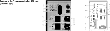
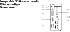
Components and functions
1. Frame rate in high speed mode when the camera is connected using two camera cables. For other conditions, please refer to the chart below.
4. Insert the cables length into _ in the model number as follows. 2 m = 2, 3 m = 3, 5 m = 5, 10 m = 10
5. The maximum cable length depends on the Camera being connected, and the model and length of the Cable being used. For further information please refer to the "Cameras/Cables" table. When a high-speed CMOS camera FH-S_02/-S_04/-S_12 is used in the high speed mode of transmission speed, two camera cables are required.
8. The FH-S___ enables switching between standard and high speed modes. In high speed mode, images can be transferred approximately two times faster than in standard mode, but the connectable cable length will be shorter.
9. The FH-S ___ has two channels to connect Camera Cables. Connection to two channels makes image transfer two times faster than connection to one channel: high speed mode using two channels can transfer approximately four times as many images as standard mode using one channel.
10. Each channel can be used to connect up to two Cable Extension Units: up to four extension units, two channels x two units, can be connected by using two channels.
12. Insert the cables length into ___ in the model number as follows. 2 m = 200, 5 m = 500, 10 m = 010.
15. Insert the cables length into ___ in the model number as follows. 0.5 m = 050, 1 m = 100, 1.5 m = 150, 2 m = 200, 3 m = 300, 5 m = 500
16. Insert the wiring method into _ in the model number as follows. Phillips screw = J, Slotted screw (rise up) = E, Push-in spring = P
Refer to the XW2R Series catalog (Cat. No. G077) for details.
17. The lineup features Low Smoke Zero Halogen cables for in-cabinet use and PUR cables for out-of-cabinet use.
20. We recommend you to use above cable for EtherCAT and EtherNet/IP, and RJ45 assembly connector together.
23. With the Vision Edition, you can use only the setup functions for FH-series/FQ-M-series vision sensors.
24. This product is a license only. You need the Sysmac Studio Standard Edition DVD media to install it.
27. Insert the aperture into _____ in the model number as follows.
F=1.9 to 3.8: blank
F=5.6: FN056
F=8: FN080
34. If compliance with EC/EU directives is required, use this interface as an analog RGB output. Refer to the manual for information on the standards.
35. The current consumption when the maximum number of cameras supported by each controller are connected. If a lighting controller model is connected to a lamp, the current consumption is as high as when an intelligent compact camera is connected.
36. When using two camera cables for connection, the maximum number of loaded images during multi-input is twice the number given in the table.
Refer to the Vision System FH/FZ5 Series User's Manual (Cat. No. Z340) for details.
37. The multi-input function cannot be used when the built-in lighting of an intelligent compact camera is used.
40. A 12-VDC power supply must be provided to the cable extension unit when connecting the Intelligent compact camera, or the Lighting controller.