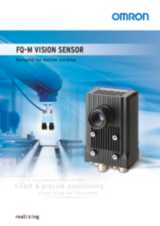
Контакты

(383)383-25-35
г. Новосибирск, мкр. Горский, 66, 2 этаж

FQ-M


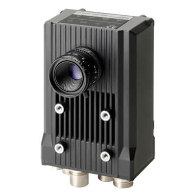
Датчики технического зрения для задач перегрузки («взять и положить»)

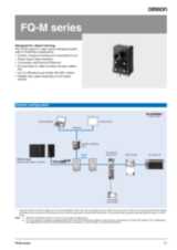
Серия FQ-M – это датчики технического зрения, разработанные специально для задач перегрузки («взять и положить»). FQ-M – это компактные быстрые датчики, связывающиеся со всеми устройствами через EtherCAT или стандартный Ethernet. Они имеют вход инкрементного энкодера для легкого отслеживания и калибровки.

  • Сделаны специально для задач перегрузки («взять и положить»)
  • Вход энкодера для конвейерного отслеживания и калибровки
  • Обнаружение объектов по форме
  • Интеллектуальный мастер калибровки
  • Программное обеспечение Sysmac Studio для эксплуатации и настройки системы технического зрения

System configuration

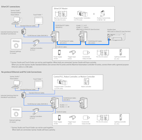
Note: 1. EtherCAT and Ethernet (PLC Link) can not be used simultaneously.

2. It is not possible to configure and adjust the FQ-M via an NJ-series controller, when they are connected via an EtherCAT network. For configuration and adjustment of FQ-M, connect the FQ-M and a computer or a Touch Finder via an Ethernet network.

Sysmac is a trademark or registered trademark of OMRON Corporation in Japan and other countries for OMRON factory automation products.

Windows is registered trademarks of Microsoft Corporation in the USA and other countries.

EtherCAT® is registered trademark and patented technology, licensed by Beckhoff Automation GmbH, Germany.

Other company names and product names in this document are the trademarks or registered trademarks of their respective companies.

Ordering Information

Sensors

Appearance

Type

Order code


Color

NPN

EtherCAT communication function not provided

FQ-MS120

PNP

FQ-MS125

Monochrome

NPN

FQ-MS120-M

PNP

FQ-MS125-M

Color

NPN

EtherCAT communication function provided

FQ-MS120-ECT

PNP

FQ-MS125-ECT

Monochrome

NPN

FQ-MS120-M-ECT

PNP

FQ-MS125-M-ECT

Automation Software Sysmac Studio

Please purchase a DVD and required number of licenses the first time you purchase the Sysmac Studio. DVDs and licenses are available individually. Each model of licenses does not include any DVD.

Product name

Specifications


Standards

Order code

Number of
licenses

Media

Sysmac Studio
Standard Edition
Ver.1. ☐☐ 1

The Sysmac Studio provides an integrated development environment to set up, program, debug, and maintain NJ-series Controllers and other Machine Automation Controllers, as well as EtherCAT slaves.


Sysmac Studio runs on the following OS.

Windows XP (Service Pack 3 or higher, 32-bit version) /
Vista (32-bit version)/7 (32-bit/64-bit version)


The Sysmac Studio Standard Edition DVD includes Support Software to set up EtherNet/IP Units,
DeviceNet slaves, Serial Communications Units, and Support Software for creating screens on HMIs (CX-Designer).

For details, refer to the Sysmac Integrated Catalogue (P072).

-
(Media only)

DVD

-

SYSMAC-SE200D

1 license2

-

-

SYSMAC-SE201L

Sysmac Studio
Vision Edition
Ver.1. ☐☐

Sysmac Studio Vision Edition is a limited license that provides selected functions required for Vision Sensor FQ-M settings.
Because this product is a license only, you need the Sysmac Studio Standard Edition DVD media to install it.

1 license

-

-

SYSMAC-VE001L

Touch Finder

Appearance

Type

Order code


DC power supply

FQ-MD30

AC/DC/battery3

FQ-MD31

Bend resistant Cables for FQ-M Series

Appearance

Type

Order code


For EtherCAT and Ethernet cable

Angle: M12/ Straight: RJ45

Cable length: 5 m

FQ-MWNL005

Cable length: 10 m

FQ-MWNL010


For EtherCAT and Ethernet cable

Straight type (M12/RJ45)

Cable length: 5m

FQ-WN005-E

Cable length: 10 m

FQ-WN010-E


For EtherCAT cable

Angle type (M12/M12)

Cable length: 5 m

FQ-MWNEL005

Cable length: 10 m

FQ-MWNEL010


For EtherCAT cable

Straight type (M12/M12)

Cable length: 5m

FQ-MWNE005

Cable length: 10 m

FQ-MWNE010


I/O Cables

Angle type

Cable length: 5 m

FQ-MWDL005

Cable length: 10 m

FQ-MWDL010


Straight type

Cable length: 5 m

FQ-MWD005

Cable length: 10 m

FQ-MWD010

Accessories

Appearance

Type

Order code


For Touch Finder

Panel Mounting Adapter

FQ-XPM


AC Adapter

(for models for DC/AC/Battery)

FQ-AC 4


Battery

(for models for DC/AC/Battery)

FQ-BAT1


Touch Pen

(enclosed with Touch Finder)

FQ-XT


Strap

FQ-XH


SD Card (2 GB)

HMC-SD291


Plug type

Voltage

Certified standards

Order code

A

125 V max.

PSE

FQ-AC1

UL/CSA

FQ-AC2

250 V max.

CCC mark

FQ-AC3

C

250 V max.

-

FQ-AC4

BF

250 V max.

-

FQ-AC5

O

250 V max.

-

FQ-AC6

Industrial Switching Hubs for EtherNet/IP and Ethernet

Appearance

Number of ports

Failure detection

Current consumption

Order code


3

None

0.22 A

W4S1-03B


5

None

0.22 A

W4S1-05B

Supported

W4S1-05C

Note: 1. Industrial switching hubs are cannot be used for EtherCAT.

EtherCAT junction slaves

Appearance

Number of ports

Power supply voltage

Current consumption

Order code


3

20.4 to 28.8 VDC

(24 VDC -15% to 20%)

0.08 A

GX-JC03


6

0.17 A

GX-JC06

Note: 1. Please do not connect EtherCAT junction slave with OMRON position control unit, Model CJ1W-NC 81/ 82.

2. EtherCAT junction slaves cannot be used for EtherNet/IP and Ethernet.

Cameras peripheral devices

Type

Order code

Cameras peripheral devices

CCTV Lenses

3Z4S-LE Series

External Lightings

FL Series

Lighting Controllers

For FL Series

FL-TCC1

Specifications

Sensors

Item

Type

EtherCAT communication function not provided

EtherCAT communication function provided

Color

Monochrome

Color

Monochrome

Model

NPN

FQ-MS120

FQ-MS120-M

FQ-MS120-ECT

FQ-MS120-M-ECT

PNP

FQ-MS125

FQ-MS125-M

FQ-MS125-ECT

FQ-MS125-M-ECT

Field of vision, Installation distance

Selecting a lens according to the field of vision and installation distance.

Main functions

Inspection items

Shape search, Search, Labeling, Edge position

Number of simultaneous inspections

32

Number of registered scenes

32

Image input

Image processing method

Real color

Monochrome

Real color

Monochrome

Image elements

1/3-inch color CMOS

1/3-inch monochrome CMOS

1/3-inch color CMOS

1/3-inch monochrome CMOS

Image filter

High dynamic range (HDR) and white balance

High dynamic range (HDR)

High dynamic range (HDR) and white balance

High dynamic range (HDR)

Shutter

Electronic shutter; select shutter speeds from 1/10 to 1/30000 (sec)

Processing resolution

752 (H) × 480 (V)

Pixel size

6.0 ( m m) × 6.0 ( m m)

Frame rate
(image read time)

60 fps (16.7 ms)

External Lightings

Connecting method

Connection via a strobe light controller

Connectable lighting

FL series

Data logging

Measurement data

In Sensor: Max. 32,000 items5

Images

In Sensor: 20 images1

Measurement trigger

I/O trigger, Encoder trigger, Communications trigger (Ethernet No-protocol, PLC Link, or EtherCAT)

I/O specifications

Input signals

9 signals

Single measurement input (TRIG)

Error clear input (IN0)

Encoder counter reset input (IN1)

Encoder input (A±, B±, Z±)6

Output signals

5 signals7

OUT0 Overall judgement output (OR)

OUT1 Control output (BUSY)

OUT2 Error output (ERROR)

OUT3 (Shutter output: SHTOUT)

OUT4 (Strobe trigger output: STGOUT)

Ethernet specifications

100BASE-TX/10BASE-TX

EtherCAT specifications

-

Dedicated protocol for EtherCAT 100BASE-TX

Connection method

Special connector cables

Power supply and I/O: 1 Special connector I/O cable

Touch Finder, Computer and Ethernet: 1 Ethernet cable

EtherCAT: 2 EtherCAT cable

LED display


OR: Judgment result indicator

ERR: Error indicator

BUSY: BUSY indicator

ETN: Ethernet communications indicator

EtherCAT display

-

L/A IN (Link/Activity IN) × 1

L/A OUT (Link/Activity OUT) × 1

RUN × 1

ERR × 1

Ratings

Power supply voltage

21.6 to 26.4 VDC (including ripple)

Insulation resistance

Between all lead wires and case: 0.5 M W (at 250 V)

Current consumption

450mA max. (When the FL-series Strobe controller and lighting are used.)

250mA max. (When external lighting is not used.)

Environmental

immunity

Ambient temperature range

Operating: 0 to 50 °C, Storage: -20 to 65 °C (with no icing or condensation)

Ambient humidity range

Operating and storage: 35% to 85% (with no condensation)

Ambient atmosphere

No corrosive gas

Vibration resistance
(destruction)

10 to 150 Hz, single amplitude: 0.35 mm, X/Y/Z directions, 8 min each, 10 times

Shock resistance
(destruction)

150 m/s2 3 times each in 6 direction (up, down, right, left, forward, and backward)

Degree of protection

IEC60529 IP40

Materials

Case: alminium die casting, Rear cover: alminium plate

Weight

Approx. 390 g (Sensor only)

Approx. 480 g (Sensor only)

Accessories

Instruction Manual

Pulse input Specifications (When an open collector type encoder is used.)

Item

Specification

Input voltage

24 VDC±10%

12 VDC±10%

5 VDC±5%

Input current

4.8 mA (at 24 VDC, typical value)

2.4 mA (at 12 VDC, typical value)

1.0 mA (at 5 VDC, typical value)

NPN

ON voltage8

4.8 V max.

2.4 V max.

1.0 V max.

OFF voltage9

19.2 V min.

9.6 V min.

4.0 V min.

PNP

ON voltage1

19.2 V min.

9.6 V min.

4.0 V min.

OFF voltage2

4.8 V max.

2.4 V max.

1.0 V max.

Maximum response frequency10

50 kHz (I/O cable: when the FQ-MWD005 or FQ-MWDL005 cables is used.)

20 kHz (I/O cable: when the FQ-MWD010 or FQ-MWDL010 cables is used.)

Input impedance

5.1 k W


Pulse input Specifications (When a line-driver output type encoder is used.)

Item

Specification

Input voltage

EIA standard RS-422-A line driver level

Input impedance11

120 W ±5%

Differential input voltage

0.2 V min.

Hysteresis voltage

50 mV

Maximum response frequency12

200 kHz (I/O cable: when the FQ-MWD005, FQ-MWDL005, FQ-MWD010, or FQ-MWDL010 cables is used.)

Touch Finder

Item

Type

Model with DC power supply

Model with AC/DC/battery power supply

Model

FQ-MD30

FQ-MD31

Number of connectable Sensors

2 max.

Main functions

Types of measurement displays

Last result display, Last NG display, trend monitor, histograms

Types of display images

Through, frozen, zoom-in, and zoom-out images

Data logging

Measurement results, measured images

Menu language

English, Japanese

Indications

LCD

Display device

3.5-inch TFT color LCD

Pixels

320 × 240

Display colors

16,777,216

Backlight

Life expectancy13

50,000 hours at 25°C

Brightness adjustment

Provided

Screen saver

Provided

Indicators

Power indicator
(color: green)

POWER

Error indicator
(color: red)

ERROR

SD card access indicator
(color: yellow)

SD ACCESS

Charge indicator
(color: orange)

-

CHARGE

Operation interface

Touch screen

Method

Resistance film

Life expectancy14

1,000,000 operations

External interface

Ethernet

100 BASE-TX/10 BASE-T

SD card

Omron SD card (Model: HMC-SD291) or a SDHC card of Class4 or higher rating is recommended.

Ratings

Power supply voltage

DC power connection

20.4 to 26.4 VDC (including ripple)

AC adapter connection

-

100 to 240 VAC, 50/60 Hz

Battery connection

-

FQ-BAT1 Battery (1 cell, 3.7 V)

Continuous operation on Battery15

-

1.5 h

Current consumption

DC power connection: 0.2 A

Insulation resistance

Between all lead wires and case: 0.5 M W (at 250 V)

Environmental
immunity

Ambient temperature range

Operating: 0 to 50°C

Storage: -25 to 65°C

(with no icing or condensation)

Operating: 0 to 50°C when mounted to DIN Track
or panel 0 to 40°C when operated on a Battery

Storage: -25 to 65°C

(with no icing or condensation)

Ambient humidity range

Operating and storage: 35% to 85% (with no condensation)

Environmental
immunity

Ambient atmosphere

No corrosive gas

Vibration resistance (destruction)

10 to 150 Hz, single amplitude: 0.35 mm, X/Y/Z directions 8 min each, 10 times

Shock resistance (destruction)

150 m/s2 3 times each in 6 direction (up, down, right, left, forward, and backward)

Degree of protection

IEC 60529 IP20

Dimensions

95 × 85 × 33 mm

Materials

Case: ABS

Weight

Approx. 270 g (without Battery and hand strap)

Accessories

Touch Pen (FQ-XT), Instruction Manual

Battery Specifications

Item Model

FQ-BAT1

Battery type

Secondary lithium ion battery

Nominal capacity

1,800 mAh

Rated voltage

3.7 V

Dimensions

35.3 × 53.1 × 11.4 mm

Ambient temperature range

Operating: 0 to 40°C

Storage: -25 to 65°C
(with no icing or condensation)

Ambient humidity range

Operating and storage: 35% to 85%
(with no condensation)

Charging method

Charged in Touch Finder (FQ-MD31).

AC adapter (FQ-AC ) is required.

Charging time16

2.0 h

Battery backup life17

300 charging cycles

Weight

50 g max.

Sysmac Studio

Item

Requirement

Operating system (OS)18, 19

Japanese or English system

Windows XP (Service Pack 3 or higher,
32-bit version) /Vista (32-bit version) /
7 (32-bit/64-bit version)

CPU

Windows computers with Celeron 540
(1.8 GHz) or faster CPU.

Core i5 M520 (2.4 GHz) or equivalent or
faster recommended

Main memory

2 GB min.

Hard disk

At least 1.6 GB of available space20

Display

XGA 1,024 × 768, 1,600 million colors.

WXGA 1,280 × 800 min. recommended

Disk drive

DVD-ROM drive

Communications ports

USB port corresponded to USB 2.0,
or Ethernet port

FQ-M Series EtherCAT Communications Specifications

Item

Specifications

Communications standard

IEC 61158 Type12

Physical layer

100BASE-TX (IEEE802.3)

Connector

M12 × 2

E-CAT IN: EtherCAT (IN)

E-CAT OUT: EtherCAT (OUT)

Communications media

Use the cables for FQ-MWN ☐☐ , or FQ-WN ☐☐ series.

Communications distance

Use the communication cable within the length of FQ-MWN ☐☐ or FQ-WN ☐☐ series cables.

Process data

Variable PDO Mapping

Mailbox (CoE)

Emergency messages, SDO requests, SDO responses, and SDO information

Distributed clock

Synchronization with DC mode 1

LED display

L/A IN (Link/Activity IN) × 1, L/A OUT (Link/Activity OUT) × 1, RUN × 1, ERR × 1

Version Information

FQ-M Series and Programming Devices


FQ-M Series

Required Programming Device

Sysmac Studio Standard Edition/Vision Edition

Ver.1.00

Ver.1.01 or higher

FQ-MS ☐☐☐ (-M)

FQ-MS ☐☐☐ (-M)-ECT

Not supported

Supported

Components and Functions

Sensor


No.

Name

Description

(1)

I/O Cable connector

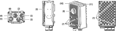
An I/O Cable is used to connect the
Sensor to the power supply and external I/O.

(2)

Ethernet connector

An Ethernet cable is used to connect the Sensor to external devices such as PLCs, the Touch Finder, or computers.

(3)

Lighting connector

Connect an external lighting (strobe controller).

(4)

EtherCAT connector (IN)21

Connect an EtherCAT compatible device.

(5)

EtherCAT connector (OUT)1

Connect an EtherCAT compatible device.

(6)

Node address switch1

Set the node address for EtherCAT communications.

(7)

Installation holes

Holes to install and secure the camera.

(8)

C-mount lens connection part

Install the C-mount lens in this part.
Determine the field of view depending on the measurement target and select a suitable CCTV lens
(C-mounting lens).


No.

Name

Description

(9)

Strobe controller
connection holes

Install the strobe controller in this part. FL-TCC1 can be mounted.

(10)

Measurement
process

Operation

indicators

OR

Lit in orange while OR signal is ON.

ETN

Lit in orange while in Ethernet communications.

ERROR

Lit in red when an error occurs.

BUSY

Lit in green while the sensor is processing.

(11)

EtherCAT

Operation

indicators

L/A IN

Lit in green when Link with EtherCAT
device is established and flickers in green when communicating (data IN).

L/A OUT

Lit in green when Link with EtherCAT
device is established and flickers in green when communicating (data OUT).

ECAT RUN

Lit in green when EtherCAT communication is available.

ECAT ERROR

Lit in red when an EtherCAT communications error occurs.

Touch Finder


No.

Name

Description

(1)

Operation

indicators

POWER

Lights green when the Touch Finder is turned ON.

ERROR

Lights red when an error occurs.

SD ACCESS

Lights yellow when an SD card is inserted.

Flashes yellow when the SD card is
being accessed.

CHARGE22

Lights orange when the Battery is charging.

(2)

LCD/touch panel

Displays the setting menu, measurement results, and images input by the camera.

(3)

SD card slot

An SD card can be inserted.

(4)

Battery cover*

The Battery is inserted behind this cover.

Remove the cover when mounting or
removing the Battery.

(5)

Power supply switch

The Battery is inserted behind this cover.

Remove the cover when mounting or
removing the Battery.


No.

Name

Description

(6)

Touch pen holder

The touch pen can be stored here when it is not being used.

(7)

Touch pen

Used to operate the touch panel.

(8)

DC power supply connector

Used to connect a DC power supply.

(9)

Slider

Used to mount the Touch Finder to a DIN Track.

(10)

Ethernet port

Used when connecting the Touch Finder to the Sensor with an Ethernet cable.
Insert the connector until it locks in place.

(11)

Strap holder

This is a holder for attaching the strap.

(12)

AC power supply connector23

Used to connect the AC adapter.


1. The FQ-M series is supported by Sysmac Studio version 1.01 or higher.

2. Multi licenses are available for the Sysmac Studio (3, 10, 30, or 50 licenses).

3. AC Adapter and Battery are sold separately.

4. AC Adapters for Touch Finder with DC/AC/Battery Power Supply. Select the model for the country in which the Touch Finder will be used.

5. If a Touch Finder is used, results can be saved up to the capacity of an SD card.

6. Encoder input specifications.

7. The five output signals can be allocated for the judgements of individual inspection items.

8. ON voltage: Voltage to change from OFF to ON state. The ON voltage is the difference of voltages between the GND terminal of the encoder power terminals and each input terminal.

9. OFF voltage: Voltage to change from ON to OFF state. The ON voltage is the difference of voltages between the GND terminal of the encoder power terminals and each input terminal.

10. Select maximum response frequency depending on length of the encoder cable and response frequency of the encoder.

11. When terminating resistance function is used.

12. Select maximum response frequency depending on length of the encoder cable and response frequency of the encoder.

13. This is a guideline for the time required for the brightness to diminish to half the initial brightness at room temperature and humidity. No guarantee is implied. The life of the backlight is greatly affected by the ambient temperature and humidity. It will be shorter at lower or higher temperatures.

14. This value is only a guideline. No guarantee is implied. The value will be affected by operating conditions.

15. This value is only a guideline. No guarantee is implied. The value will be affected by the operating environment and operating conditions.

16. This value is only a guideline. No guarantee is implied. The value will be affected by operating conditions.

17. This is a guideline for the time required for the capacity of the Battery to be reduced to 60% of the initial capacity. No guarantee is implied.The value will be affected by the operating environment and operating conditions.

18. Sysmac Studio Operating System Precaution:
System requirements and hard disk space may vary with the system environment.

19. The following restrictions apply when Sysmac Studio is used with Microsoft Windows Vista or Windows 7.
Some Help files cannot be accessed.
The Help files can be accessed if the Help program distributed by Microsoft for Windows (WinHlp32.exe) is installed. Refer to the Microsoft homepage listed below or contact Microsoft for details on installing the file. (The download page is automatically displayed if the Help files are opened while the user is connected to the Internet.)
http://support.microsoft.com/kb/917607/en-us

20. To use the file logging function, additional memory area to save the logging data is necessary.

21. FQ-MS ☐☐☐ -ECT and FQ-MS ☐☐☐ -M-ECT only.

22. Applicable to the FQ-MD31 only.

23. Applicable to the FQ-MD31 only.

Регистрация и загрузка программного обеспечения

software engineer 2 prod
В этом разделе на нашем веб-сайте вы сможете зарегистрировать ваше программное обеспечение Omron. После регистрации номера лицензии вы получите доступ к соответствующим файлам обновления и поддержки. Также в этом разделе можно бесплатно загрузить несколько программных приложений и инструментов.