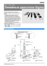
Ordering information
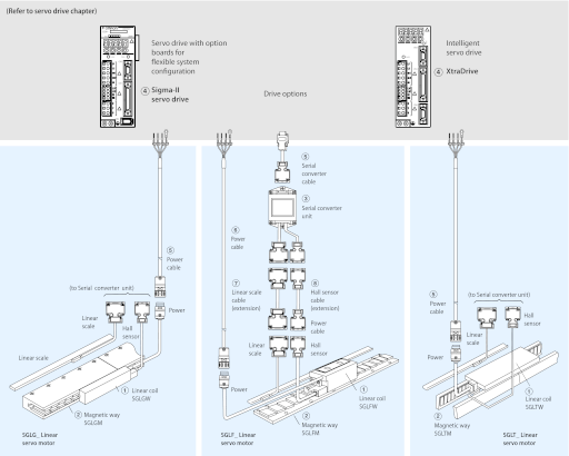
Note: The symbols ① ② ③ ... show the recommended sequence to select the servo motor, cables and serial converter for a linear motor system
Servo motor
GLGW/SGLGM coreless type (200 V)
With standard-force magnetic ways - 230VAC single phase
| Symbol | Specifications | Order code |
| Rated force | Peak force | ① Linear coil | ② Magnetic way | ③ Serial converter | ④ Servo drive |
| Sigma-II series | XtraDrive |
| ① ② ③ ④ | 13.5 N | 40 N | SGLGW-30A050CPD | SGLGM-30108A SGLGM-30216A SGLGM-30432A | JZDP-D008-250 | SGDH-A5AE-OY | XD-P5-MN01 |
| 27 N | 80 N | SGLGW-30A080CPD | JZDP-D008-251 | SGDH-01AE-OY | XD-01-MN01 |
| 47 N | 140 N | SGLGW-40A140CPD | SGLGM-40090CT SGLGM-40225CT SGLGM-40360CT SGLGM-40405CT SGLGM-40450CT | JZDP-D008-252 | SGDH-01AE-OY | XD-01-MN01 |
| 93 N | 280 N | SGLGW-40A253CPD | JZDP-D008-253 | SGDH-02AE-OY | XD-02-MN01 |
| 140 N | 420 N | SGLGW-40A365CPD | JZDP-D008-254 | SGDH-04AE-OY | XD-04-MN01 |
| 73 N | 220 N | SGLGW-60A140CPD | SGLGM-60090CT SGLGM-60225CT SGLGM-60360CT SGLGM-60405CT SGLGM-60450CT | JZDP-D008-258 | SGDH-02AE-OY | XD-02-MN01 |
| 147 N | 440 N | SGLGW-60A253CPD | JZDP-D008-259 | SGDH-04AE-OY | XD-04-MN01 |
| 220 N | 660 N | SGLGW-60A365CPD | JZDP-D008-260 | SGDH-08AE-S-OY | XD-08-MN |
| 325 N | 1300 N | SGLGW-90A200CPD | SGLGM-90252A SGLGM-90504A | JZDP-D008-260 | SGDH-15AE-S-OY | XD-15-MN |
- Note • Linear coils with design revision C are equivalent to previous versions. The serial converter required for revision C coil has changed from previous version, select it according to the table above.
- • Magnetic ways with design revision C and revision B can be combined.
With high-force magnetic ways - 230VAC single phase
| Symbol | Specifications | Order code |
| Rated force | Peak force | ① Linear coil | ② Magnetic way | ③ Serial converter | ④ Servo drive |
| Sigma-II series | XtraDrive |
| ① ② ③ ④ | 57 N | 230 N | SGLGW-40A140CPD | SGLGM-40090CT-M SGLGM-40225CT-M SGLGM-40360CT-M SGLGM-40405CT-M SGLGM-40450CT-M | JZDP-D008-255 | SGDH-02AE-OY | XD-02-MN01 |
| 114 N | 460 N | SGLGW-40A253CPD | JZDP-D008-256 | SGDH-04AE-OY | XD-04-MN01 |
| 171 N | 690 N | SGLGW-40A365CPD | JZDP-D008-257 | SGDH-08AE-S-OY | XD-08-MN |
| 89 N | 360 N | SGLGW-60A140CPD | SGLGM-60090CT-M SGLGM-60225CT-M SGLGM-60360CT-M SGLGM-60405CT-M SGLGM-60450CT-M | JZDP-D008-261 | SGDH-02AE-OY | XD-02-MN01 |
| 178 N | 720 N | SGLGW-60A253CPD | JZDP-D008-262 | SGDH-08AE-S-OY | XD-08-MN |
| 267 N | 1080 N | SGLGW-60A365CPD | JZDP-D008-263 | SGDH-15AE-S-OY | XD-15-MN |
- Note • Linear coils with design revision C are equivalent to previous versions. The serial converter required for revision C coil has changed from previous version, select it according to the table above.
- • Magnetic ways with design revision C and revision B can be combined.
SGLFW/SGLFM iron-core type
230 VAC single phase
| Symbol | Specifications | Order code |
| Rated force | Peak force | ① Linear coil | ② Magnetic way | ③ Serial converter | ④ Servo drive |
| Sigma-II series | XtraDrive |
| ① ② ③ ④ | 25 N | 86 N | SGLFW-20A090APD | SGLFM-20324AC SGLFM-20540AC SGLFM-20756AC | JZDP-A008-017 | SGDH-02AE-OY | XD-02-MN01 |
| 40 N | 125 N | SGLFW-20A120APD | JZDP-A008-018 | SGDH-02AE-OY | XD-02-MN01 |
| 80 N | 220 N | SGLFW-35A120APD | SGLFM-35324AC SGLFM-35540AC SGLFM-35756AC | JZDP-A008-019 | SGDH-02AE-OY | XD-02-MN01 |
| 160 N | 440 N | SGLFW-35A230APD | JZDP-A008-020 | SGDH-08AE-S-OY | XD-08-MN01 |
| 280 N | 600 N | SGLFW-50A200BPD | SGLFM-50405AC SGLFM-50675AC SGLFM-50945AC | JZDP-A008-181 | SGDH-08AE-S-OY | XD-08-MN |
| 560 N | 1200 N | SGLFW-50A380BPD | JZDP-A008-182 | SGDH-15AE-S-OY | XD-15-MN |
| 560 N | 1200 N | SGLFW-1ZA200BPD | SGLFM-1Z405AC SGLFM-1Z675AC SGLFM-1Z945AC | JZDP-A008-183 | SGDH-15AE-S-OY | XD-15-MN |
Note: Serial converters with design revision A (JZDP-A008-xxx) will be replaced by revision D (JZDP-D008-xxx), both models are fully compatible.
400 VAC three phase
| Symbol | Specifications | Order code |
| Rated force | Peak force | ① Linear coil | ② Magnetic way | ③ Serial converter | ④ Servo drive |
| Sigma-II series | XtraDrive |
| ① ② ③ ④ | 80 N | 220 N | SGLFW-35D120APD | SGLFM-35324AC SGLFM-35540AC SGLFM-35756AC | JZDP-A008-211 | SGDH-05DE-OY | XD-05-TN |
| 160 N | 440 N | SGLFW-35D230APD | JZDP-A008-212 | SGDH-05DE-OY | XD-05-TN |
| 280 N | 600 N | SGLFW-50D200BPD | SGLFM-50405AC SGLFM-50675AC SGLFM-50945AC | JZDP-A008-189 | SGDH-10DE-OY | XD-10-TN |
| 560 N | 1200 N | SGLFW-50D380BPD | JZDP-A008-190 | SGDH-15DE-OY | XD-15-TN |
| 560 N | 1200 N | SGLFW-1ZD200BPD | SGLFM-1Z405AC SGLFM-1Z675AC SGLFM-1Z945AC | JZDP-A008-191 | SGDH-15DE-OY | XD-15-TN |
| 1120 N | 2400 N | SGLFW-1ZD380BPD | JZDP-A008-192 | SGDH-30DE-OY | XD-30-TN |
| 1500 N | 3600 N | SGLFW-1ED380BP | SGLFM-1E135AC | JZDP-D008-333 | SGDH-20DE-OY | XD-20-TN |
| 2250 N | 5400 N | SGLFW-1ED560BP | JZDP-D008-334 | SGDH-30DE-OY | XD-30-TN |
Note: Serial converters with design revision A (JZDP-A008-xxx) will be replaced by revision D (JZDP-D008-xxx), both models are fully compatible.
SGLTW/SGLTM iron-core type
400 VAC three phase
| Symbol | Specifications | Order code |
| Rated force | Peak force | ① Linear coil | ② Magnetic way | ③ Serial converter | ④ Servo drive |
| Sigma-II series | XtraDrive |
| ① ② ③ ④ | 300 N | 600 N | SGLTW-35D170HPD | SGLTM-35324HC SGLTM-35540HC SGLTM-35756HC | JZDP-A008-193 | SGDH-10DE-OY | XD-10-TN |
| 600 N | 1200 N | SGLTW-35D320HPD | JZDP-A008-194 | SGDH-20DE-OY | XD-20-TN |
| 450 N | 900 N | SGLTW-50D170HPD | SGLTM-50324HC SGLTM-50540HC SGLTM-50756HC | JZDP-A008-195 | SGDH-10DE-OY | XD-10-TN |
| 900 N | 1800 N | SGLTW-50D320HPD | JZDP-A008-196 | SGDH-20DE-OY | XD-20-TN |
| 670 N | 2600 N | SGLTW-40D400BP | SGLTM-40405AC SGLTM-40675AC SGLTM-40945AC | JZDP-A008-197 | SGDH-30DE-OY | XD-30-TN |
| 1000 N | 4000 N | SGLTW-40D600BP | JZDP-A008-198 | SGDH-50DE-OY | XD-50-TN |
| 1300 N | 5000 N | SGLTW-80D400BP | SGLTM-80405AC SGLTM-80675AC SGLTM-80945AC | JZDP-A008-199 | SGDH-50DE-OY | XD-50-TN |
| 2000 N | 7500 N | SGLTW-80D600BP | JZDP-A008-200 | SGDH-75DE-OY | − |
Note: Serial converters with design revision A (JZDP-A008-xxx) will be replaced by revision D (JZDP-D008-xxx), both models are fully compatible.
Servo drive
Note: Choosing Sigma-II drive or XtraDrive affects to the serial converter cable needed.
④ Refer to Sigma-II servo drive or XtraDrive chapter for detailed drive specifications and selection of drive accessories.
Serial converter cable to servo drive
| Symbol | Appearance | Specifications | Order code |
| ⑤ |  | Sigma-II drive to serial converter cable | 3 m | JZSP-CLP70-03-E |
| 5 m | JZSP-CLP70-05-E |
| 10 m | JZSP-CLP70-10-E |
| 15 m | JZSP-CLP70-15-E |
| 20 m | JZSP-CLP70-20-E |
| 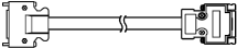 | XtraDrive drive to serial converter cable | 3 m | XD-CLP70-03-E |
| 5 m | XD-CLP70-05-E |
| 10 m | XD-CLP70-10-E |
| 15 m | XD-CLP70-15-E |
| 20 m | XD-CLP70-20-E |
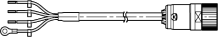
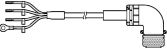
Power cables
| Symbol | Appearance | Specifications | Order code |
| ⑥ | 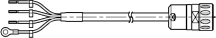 | For 200 V servo motors SGLGW-30A_____D SGLGW-40A_____D SGLGW-60A_____D SGLFW-20A___A_D SGLFW-35A___A_D | 3 m | R88A-CAWA003S-DE |
| 5 m | R88A-CAWA005S-DE |
| 10 m | R88A-CAWA010S-DE |
| 15 m | R88A-CAWA015S-DE |
| 20 m | R88A-CAWA020S-DE |
|  | For 200 V servo motors SGLGW-90A200__D SGLFW-50A___B_D SGLFW-1ZA200B_D | 3 m | R88A-CAWB003S-DE |
| 5 m | R88A-CAWB005S-DE |
| 10 m | R88A-CAWB010S-DE |
| 15 m | R88A-CAWB015S-DE |
| 20 m | R88A-CAWB020S-DE |
| 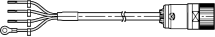 | For 400 V servo motors SGLFW-35D___A_D SGLFW-50D200_D SGLTW-35D170H_D SGLTW-50D170H_D | 3 m | R88A-CAWK003S-DE |
| 5 m | R88A-CAWK005S-DE |
| 10 m | R88A-CAWK010S-DE |
| 15 m | R88A-CAWK015S-DE |
| 20 m | R88A-CAWK020S-DE |
|  | For 400 V servo motors SGLFW-50D380_D SGLFW-1ZD___B_D SGLTW-35D320H_D SGLTW-50D320H_D | 3 m | R88A-CAWL003S-DE |
| 5 m | R88A-CAWL005S-DE |
| 10 m | R88A-CAWL010S-DE |
| 15 m | R88A-CAWL015S-DE |
| 20 m | R88A-CAWL020S-DE |
|  | For 400 V servo motors SGLFW-1ED___B_ SGLTW-40D___B_ SGLTW-80D___B_ | 3 m | R88A-CAWD003S-E |
| 5 m | R88A-CAWD005S-E |
| 10 m | R88A-CAWD010S-E |
| 15 m | R88A-CAWD015S-E |
| 20 m | R88A-CAWD020S-E |
Linear scale cable to serial converter
| Symbol | Appearance | Specifications | Order code |
| ⑦ | 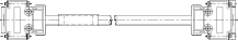 | Extension cable for Renishaw linear scale to serial
converter. (connector DB-15) (the extension cable is optional) | 1 m | JZSP-CLL00-01-E |
| 3 m | JZSP-CLL00-03-E |
| 5 m | JZSP-CLL00-05-E |
| 10 m | JZSP-CLL00-10-E |
| 15 m | JZSP-CLL00-15-E |
| Extension cable for Heidenhain linear scale to serial
converter (connector DB-15) (when a Heidenhain scale is used the extension cable is required) | 1 m | JZSP-CLL20-01-E |
| 3 m | JZSP-CLL20-03-E |
| 5 m | JZSP-CLL20-05-E |
| 10 m | JZSP-CLL20-10-E |
| 15 m | JZSP-CLL20-15-E |
Hall sensor cable to serial converter
| Symbol | Appearance | Specifications | Order code |
| ⑧ | 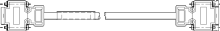 | Extension cable for linear scale to serial converter (the extension cable is optional) | 1 m | JZSP-CLL10-01-E |
| 3 m | JZSP-CLL10-03-E |
| 5 m | JZSP-CLL10-05-E |
| 10 m | JZSP-CLL10-10-E |
| 15 m | JZSP-CLL10-15-E |
Connectors
| Specification | Order code |
| Hypertac power connector IP67 (for 200V motor coils SGL_W-__A_____D) | SPOC-06K-FSDN169 |
| Hypertac power connector IP67 (for 400V motor coils SGL_W-__D_____D) | LPRA-06B-FRBN170 |
| Military power connector IP67 (for motor coils SGLTW-40_/80_ and SGLFW-1ED_) | MS3108E22-22S |
Dimensioning software
| Specifications | Order code |
| SigmaSize | MOTION TOOLS CD |
Servo motor specifications
Coreless SGLGW/SGLGM - (with standard-force magnetic ways)
| Voltage | 230 V |
| Linear servo motor model SGLGW- | 30A | 40A | 60A | 90A |
| 050C | 080C | 140C | 253C | 365C | 140C | 253C | 365C | 200C |
| Rated force ∗ | N | 12.5 | 25 | 47 | 93 | 140 | 70 | 140 | 210 | 325 |
| Rated current ∗ | A(rms) | 0,51 | 0,79 | 0.8 | 1.6 | 2.4 | 1,16 | 2,2 | 3,3 | 4.4 |
| Instantaneous peak force ∗ | N | 40 | 80 | 140 | 280 | 420 | 220 | 440 | 660 | 1300 |
| Instantaneous peak current ∗ | A(rms) | 1.62 | 2.53 | 2.4 | 4.9 | 7.3 | 3.5 | 7.0 | 10.5 | 17.6 |
| Coil assembly mass | kg | 0.10 | 0.15 | 0.34 | 0.60 | 0.87 | 0.42 | 0.76 | 1.10 | 2.15 |
| Force constant | N/A(rms) | 26.4 | 33.9 | 61.5 | 61.5 | 61.5 | 66.6 | 66.6 | 66.6 | 78 |
| BEMF constant | V/(m/s) | 8.8 | 11.3 | 20.5 | 20.5 | 20.5 | 22.2 | 22.2 | 22.2 | 26.0 |
| Motor constant |  | 3.7 | 5.6 | 7.8 | 11.0 | 13.5 | 11.1 | 15.7 | 19.2 | 26.0 |
| Electrical time constant | ms | 0.2 | 0.4 | 0.4 | 0.4 | 0.4 | 0.5 | 0.5 | 0.5 | 1.4 |
| Mechanical time constant | ms | 7.30 | 4.78 | 5.59 | 4.96 | 4.77 | 3.41 | 3.08 | 2.98 | 3.18 |
| Thermal resistance (with heat sink) | K/W | 5,19 | 3,11 | 1,67 | 0,87 | 0,58 | 1,56 | 0,77 | 0,51 | 0,39 |
| Thermal resistance (without heat sink) | K/W | − | − | 3,02 | 1,80 | 1,23 | 2,59 | 1,48 | 1,15 | − |
| Magnetic attraction | N | 0 | 0 | 0 | 0 | 0 | 0 | 0 | 0 | 0 |
| Heat sink size (H×W×D) | mm | 200×300×12 | 300×400×12 | 400×500×12 | 200×300×12 | 300×400×12 | 400×500×12 | 800×900×12 |
| Basic specifications | Time rating | Continuous |
| Insulation class | Class B |
| Ambient temperature | 0 to +40°C |
| Ambient humidity | 20 to 80% (non-condensing) |
| Insulation resistance | 500 VDC, 10 MΩ min. |
| Excitation | Permanent magnet |
| Dielectric strength | 1500 VAC for 1 minute |
| Protection methods | Self-cooled, air-cooling |
| Allowable winding temperature | 130°C |
- Note • The items marked with an * and “force and speed characteristics” are the values at a motor winding temperature of 100 ° C during operation in combination with a servo drive. The others are at 20 ° C (68 ° F).
- • The above specifications show the values under the cooling condition when a heat sink (aluminium board) listed in the following table is mounted on the coil assembly.
Coreless SGLGW/SGLGM - (with high-force magnetic ways)
| Voltage | 230 V |
| Linear servo motor model SGLGW- | 40A | 60A |
| 140C | 253C | 365C | 140C | 253C | 365C |
| Rated force ∗ | N | 57 | 114 | 171 | 85 | 170 | 255 |
| Rated current ∗ | A(rms) | 0.8 | 1.6 | 2.4 | 1.2 | 2.2 | 3.3 |
| Instantaneous peak force ∗ | N | 230 | 460 | 690 | 360 | 720 | 1080 |
| Instantaneous peak current ∗ | A(rms) | 3.2 | 6.5 | 9.7 | 5.0 | 10.0 | 14.9 |
| Coil assembly mass | kg | 0.34 | 0.60 | 0.87 | 0.42 | 0.76 | 1.10 |
| Force constant | N/A(rms) | 76.0 | 76.0 | 76.0 | 77.4 | 77.4 | 77.4 |
| BEMF constant | V/(m/s) | 25.3 | 25.3 | 25.3 | 25.8 | 25.8 | 25.8 |
| Motor constant |  | 9.6 | 13.6 | 16.7 | 12.9 | 18.2 | 22.3 |
| Electrical time constant | ms | 0.4 | 0.4 | 0.4 | 0.5 | 0.5 | 0.5 |
| Mechanical time constant | ms | 3.69 | 3.24 | 3.12 | 2.52 | 2.29 | 2.21 |
| Thermal resistance (with heat sink) | K/W | 1.67 | 0.87 | 0.58 | 1.56 | 0.77 | 0.51 |
| Thermal resistance (without heat sink) | K/W | 3.02 | 1.80 | 1.23 | 2.59 | 1.48 | 1.15 |
| Magnetic attraction | N | 0 | 0 | 0 | 0 | 0 | 0 |
| Heat sink size (H×W×D) | mm | 200×300×12 | 300×400×12 | 400×500×12 | 200×300×12 | 300×400×12 | 400×500×12 |
| Basic specifications | Time rating | Continuous |
| Insulation class | Class B |
| Ambient temperature | 0 to +40°C |
| Ambienthumidity | 20 to 80% (non-condensing) |
| Insulation resistance | 500 VDC, 10 MΩ min. |
| Excitation | Permanent magnet |
| Dielectric strength | 1500 VAC for 1 minute |
| Protection methods | Self-cooled, air-cooling |
| Allowable winding temperature | 130°C |
- Note • The item servo drive. The others are at 20 ° C (68 ° F).
- • The above specifications show the values under the cooling condition when a heat sink (aluminium board) listed in the following table is mounted on the coil assembly.
Iron-core SGLFW/SGLFM (200V)
| Voltage | 230 V |
| Linear servo motor model SGLFW- | 20A | 35A | 50A | 1ZA |
| 090A | 120A | 120A | 230A | 200B | 380B | 200B |
| Rated force ∗ | N | 25 | 40 | 80 | 160 | 280 | 560 | 560 |
| Rated current ∗ | A(rms) | 0.7 | 0.8 | 1.4 | 2.8 | 5.0 | 10.0 | 8.7 |
| Instantaneous peak force ∗ | N | 86 | 125 | 220 | 440 | 600 | 1200 | 1200 |
| Instantaneous peak current ∗ | A(rms) | 3.0 | 2.9 | 4.4 | 8.8 | 12.4 | 25.0 | 21.6 |
| Coil assembly mass | kg | 0.7 | 0.9 | 1.3 | 2.3 | 3.5 | 6.9 | 6.4 |
| Force constant | N/A(rms) | 36.0 | 54.0 | 62.4 | 62.4 | 60.2 | 60.2 | 69.0 |
| BEMF constant | V/(m/s) | 12.0 | 18.0 | 20.8 | 20.8 | 20.1 | 20.1 | 23.0 |
| Motor constant |  | 7.9 | 9.8 | 14.4 | 20.4 | 34.3 | 48.5 | 52.4 |
| Electrical time constant | ms | 3.2 | 3.3 | 3.6 | 3.6 | 15.9 | 15.8 | 18.3 |
| Mechanical time constant | ms | 11.0 | 9.3 | 6.2 | 5.5 | 3.0 | 2.9 | 2.3 |
| Thermal resistance (with heat sink) | K/W | 4.35 | 3.19 | 1.57 | 0.96 | 0.82 | 0.32 | 0.6 |
| Thermal resistance (without heat sink) | K/W | 7.69 | 5.02 | 4.10 | 1.94 | 1.48 | 0.74 | 0.92 |
| Magnetic attraction | N | 314 | 462 | 809 | 1586 | 1650 | 3260 | 3300 |
| Heat sink size (H×W×D) | mm | 125×125×13 | 254×254×25 | 400×500×40 | 254×254×25 |
| Basic specifications | Time rating | Continuous |
| Insulation class | Class B |
| Ambient temperature | 0 to +40°C |
| Ambient humidity | 20 to 80% (non-condensing) |
| Insulation resistance | 500 VDC, 10 MΩ min. |
| Excitation | Permanent magnet |
| Dielectric strength | 1500 VAC for 1 minute |
| Protection methods | Self-cooled |
| Allowable winding temperature | 130°C |
- Note • The items marked with an * and “Force and speed characteristics” are the values at a motor winding temperature of 100 ° C during operation in combination with a servo drive. The others are at 20 ° C (68 ° F).
- • The above specifications show the values under the cooling condition when a heat sink (aluminium board) listed in the following table is mounted on the coil assembly.
Iron-core SGLFW/SGLFM (400V)
| Voltage | 400 V |
| Linear servo motor model SGLFW- | 35D | 50D | 1ZD | 1ED |
| 120A | 230A | 200B | 380B | 200B | 380B | 380B | 560B |
| Rated force ∗ | N | 80 | 160 | 280 | 560 | 560 | 1,120 | 1,500 | 2,250 |
| Rated current ∗ | A(rms) | 0.7 | 1.4 | 2.3 | 4.5 | 4.9 | 9.8 | 6.4 | 9.6 |
| Instantaneous peak force ∗ | N | 220 | 440 | 600 | 1,200 | 1,200 | 2,400 | 3,600 | 5,400 |
| Instantaneous peak current ∗ | A(rms) | 2.3 | 4.6 | 5.6 | 11.0 | 12.3 | 24.6 | 18.1 | 27.2 |
| Coil assembly mass | kg | 1.3 | 2.3 | 3.5 | 6.9 | 6.4 | 11.5 | 22.0 | 33.0 |
| Force constant | N/A(rms) | 120.2 | 120.2 | 134.7 | 134.7 | 122.6 | 122.6 | 250 | 250 |
| BEMF constant | V/(m/s) | 40.1 | 40.1 | 44.9 | 44.9 | 40.9 | 40.9 | 83.2 | 83.2 |
| Motor constant |  | 13.8 | 19.5 | 33.4 | 47.2 | 51.0 | 72.1 | 95.4 | 117 |
| Electrical time constant | ms | 3.5 | 3.5 | 15.0 | 15.0 | 17.4 | 17.2 | 19.7 | 19.6 |
| Mechanical time constant | ms | 5.5 | 5.5 | 3.2 | 3.2 | 2.5 | 2.2 | 1.8 | 1.8 |
| Thermal resistance (with heat sink) | K/W | 1.57 | 0.96 | 0.82 | 0.32 | 0.6 | 0.28 | 0.21 | 0.13 |
| Thermal resistance (without heat sink) | K/W | 4.1 | 1.94 | 1.48 | 0.74 | 0.92 | 0.55 | 0.50 | 0.35 |
| Magnetic attraction | N | 810 | 1,590 | 1,650 | 3,260 | 3,300 | 6,520 | 9,780 | 14,600 |
| Heat sink size (H×W×D) | mm | 254×254×25 | 400×500×40 | 254×254×25 | 400×500×40 | 609×762×50 | 762×1270×64 |
| Basic specifications | Time rating | Continuous |
| Insulation class | Class B |
| Ambient temperature | 0 to +40°C |
| Ambient humidity | 20 to 80% (non-condensing) |
| Insulation resistance | 500 VDC, 10 M Ω min. |
| Excitation | Permanent magnet |
| Dielectric strength | 1500 VAC for 1 minute |
| Protection methods | Self-cooled |
| Allowable winding temperature | 130°C |
- Note • The items marked with an * and “force and speed characteristics” are the values at a motor winding temperature of 100 ° C during operation in combination with a servo drive. The others are at 20 ° C (68 ° F).
- • The above specifications show the values under the cooling condition when a heat sink (aluminium board) listed in the following table is mounted on the coil assembly.
Iron-core SGLTW/SGLTM (400 V)
| Voltage | 400 V |
| Linear servo motor model SGLTW- | 35D | 50D | 40D | 80D |
| 170H | 320H | 170H | 320H | 400B | 600B | 400B | 600B |
| Rated force ∗ | N | 300 | 600 | 450 | 900 | 670 | 1,000 | 1,300 | 2,000 |
| Rated current ∗ | A(rms) | 3.2 | 6.5 | 3.2 | 6.3 | 3.7 | 5.5 | 7.2 | 11.1 |
| Instantaneous peak force ∗ | N | 600 | 1,200 | 900 | 1,800 | 2,600 | 4,000 | 5,000 | 7,500 |
| Instantaneous peak current ∗ | A(rms) | 7.5 | 15.1 | 7.3 | 14.6 | 20.7 | 30.6 | 37.6 | 56.4 |
| Coil assembly mass | kg | 4.7 | 8.8 | 6 | 11 | 15 | 23 | 25 | 36 |
| Force constant | N/A(rms) | 99.6 | 99.6 | 153.3 | 153.3 | 196.1 | 196.1 | 194.4 | 194.4 |
| BEMF constant | V/(m/s) | 33.2 | 33.2 | 51.1 | 51.1 | 65.4 | 65.4 | 64.8 | 64.8 |
| Motor constant |  | 36.3 | 51.4 | 48.9 | 69.1 | 59.6 | 73 | 85.9 | 105.2 |
| Electrical time constant | ms | 14.3 | 14.3 | 15.6 | 15.6 | 14.4 | 14.4 | 15.4 | 15.4 |
| Mechanical time constant | ms | 3.5 | 3.5 | 2.5 | 2.5 | 4.2 | 4.2 | 3.2 | 3.2 |
| Thermal resistance (with heat sink) | K/W | 0.76 | 0.4 | 0.61 | 0.3 | 0.24 | 0.2 | 0.22 | 0.18 |
| Thermal resistance (without heat sink) | K/W | 1.26 | 0.83 | 0.97 | 0.8 | 0.57 | 0.4 | 0.47 | 0.33 |
| Magnetic attraction | N | 0 | 0 | 0 | 0 | 0 | 0 | 0 | 0 |
| Magnetic attraction | N | 1,400 | 2,780 | 2,000 | 3,980 | 3,950 | 5,890 | 7,650 | 11,400 |
| Heat sink size (H×W×D) | mm | 400×500×40 | 609×762×50 |
| Basic specifications | Time rating | Continuous |
| Insulation class | Class B |
| Ambient temperature | 0 to +40°C |
| Ambient humidity | 20 to 80% (non-condensing) |
| Insulation resistance | 500 VDC, 10 MΩ min. |
| Excitation | Permanent magnet |
| Dielectric strength | 1500 VAC for 1 minute |
| Protection methods | Self-cooled |
| Allowable winding temperature | 130°C |
- Note • The items marked with an * and “force and speed characteristics” are the values at a motor winding temperature of 100°C during operation in combination with a servo drive.
The others are at 20°C (68°F). - • The above specifications show the values under the cooling condition when a heat sink (aluminium board) listed in the following table is mounted on the coil assembly.
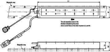
Dimensions
Coreless SGLG_-_
Coil assembly: SGLGW-_
| Coil assembly model SGLGW- | L1 | L2 | L3 | L4 | D1 | D2 | W | Approx. weight kg |
| 30A050__D | 50 | 48 | 30 | 15 | 48.5 | 57 | 22 | 0.14 |
| 30A080__D | 80 | 72 | 50 | 15 | 48.5 | 57 | 22 | 0.19 |
| 40A140__D | 140 | 125 | 90 | 30 | 63 | 78 | 25.4 | 0.40 |
| 40A253__D | 252.5 | 237.5 | 180 | 37.5 | 63 | 78 | 25.4 | 0.66 |
| 40A365__D | 365 | 350 | 315 | 30 | 63 | 78 | 25.4 | 0.93 |
| 60A140__D | 140 | 125 | 90 | 30 | 83 | 98 | 25.4 | 0.48 |
| 60A253__D | 252.5 | 237.5 | 180 | 37.5 | 83 | 98 | 25.4 | 0.82 |
| 60A365__D | 365 | 350 | 315 | 30 | 83 | 98 | 25.4 | 1.16 |
| 90A200__D | 199 | 189 | 130 | 40 | 121 | 138 | 49 | 2.2 |
Magnetic way: SGLGM-_
| Magnetic way model SGLGM- | L1 | D | Standard-force magnetic way | High-force magnetic way |
| W | Approx. weight kg | W | Approx. weight kg |
| 30108A | 108 | 44 | 24 | 0.6 | − | − |
| 30216A | 216 | 44 | 24 | 1.1 | − | − |
| 30432A | 432 | 44 | 24 | 2.3 | − | − |
| 40090C_ | 90 | 62 | 25.4 | 0.8 | 31.8 | 1.0 |
| 40225C_ | 225 | 62 | 25.4 | 2.0 | 31.8 | 2.6 |
| 40360C_ | 360 | 62 | 25.4 | 3.1 | 31.8 | 4.1 |
| 40405C_ | 405 | 62 | 25.4 | 3.5 | 31.8 | 4.6 |
| 40450C_ | 450 | 62 | 25.4 | 3.9 | 31.8 | 5.1 |
| 60090C_ | 90 | 82 | 25.4 | 1.1 | 31.8 | 1.3 |
| 60225C_ | 225 | 82 | 25.4 | 2.6 | 31.8 | 3.3 |
| 60360C_ | 360 | 82 | 25.4 | 4.1 | 31.8 | 5.2 |
| 60405C_ | 405 | 82 | 25.4 | 4.6 | 31.8 | 5.9 |
| 60450C_ | 450 | 82 | 25.4 | 5.1 | 31.8 | 6.6 |
| 90252A | 252 | 110 | 50.8 | 7.3 | − | − |
| 90504A | 504 | 110 | 50.8 | 14.7 | − | − |
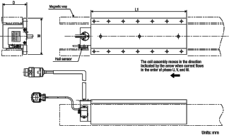
Iron-core SGLF_-_
Coil assembly: SGLFW-_
| Coil assembly model SGLFW- | L1 | D1 | D2 | W | Approx. weight kg |
| 20A090A_ | 91 | 34 | 45 | 40 | 0.7 |
| 20A120A_ | 127 | 34 | 45 | 40 | 0.9 |
| 35_120A_D | 127 | 34 | 45 | 55 | 1.3 |
| 35_230A_D | 235 | 34 | 45 | 55 | 2.3 |
| 50_200B_D | 215 | 43 | 58 | 71.5 | 3.5 |
| 50_380B_D | 395 | 43 | 58 | 71.5 | 6.9 |
| 1Z_200B_D | 215 | 43 | 58 | 119 | 6.4 |
| 1ZD380B_D | 395 | 43 | 58 | 119 | 11.5 |
| 1ED380B_ | 395 | 61 | 76 | 175 | 22 |
| 1ED560B_ | 605 | 61 | 76 | 175 | 33 |
Magnetic way: SGLFM-_
| Magnetic way model SGLFM- | L1 -0.1
-0.3 | (L3) | D | W | Approx. weight kg |
| 20324A | 324 | (331.6) | 10 | 44 | 0.9 |
| 20540A | 540 | (547.6) | 10 | 44 | 1.4 |
| 20756A | 756 | (763.6) | 10 | 44 | 2 |
| 35324A | 324 | (334.4) | 10 | 60 | 1.2 |
| 35540A | 540 | (550.4) | 10 | 60 | 2 |
| 35756A | 756 | (766.4) | 10 | 60 | 2.9 |
| 50405A | 405 | (416.3) | 14 | 75 | 2.8 |
| 50675A | 675 | (686.3) | 14 | 75 | 4.6 |
| 50945A | 945 | (956.3) | 14 | 75 | 6.5 |
| 1Z405A | 405 | (423.9) | 14 | 125 | 7.3 |
| 1Z675A | 675 | (693.9) | 14 | 125 | 12 |
| 1Z945A | 945 | (963.9) | 14 | 125 | 17 |
| 1E135A | 135 | (145.5) | 14.2 | 200 | 2.4 |
Iron-core SGLT_-_
Coil assembly: SGLTW-_
| Coil assembly model SGLTW- | L1 | D | W | Approx. weight kg |
| 35D320H_D | 315 | 66 | 120 | 8.8 |
| 50D170H_D | 170 | 81 | 120 | 6 |
| 50D320H_D | 315 | 81 | 120 | 11 |
| 40D400B_ | 395 | 78 | 150 | 15 |
| 40D600B_ | 585 | 78 | 150 | 23 |
| 80D400B_ | 395 | 115 | 150 | 25 |
| 80D600B_ | 585 | 115 | 150 | 36 |
Magnetic way: SGLTM-_
| Magnetic way model SGLTM- | L1 -0.1
-0.3 | D | W1 | W2 | W3 | Approx. weight kg |
| 35324H | 324 | 55 | 15 | 90 | 107 | 4.8 |
| 35540H | 540 | 55 | 15 | 90 | 107 | 8 |
| 35756H | 756 | 55 | 15 | 90 | 107 | 11 |
| 50324H | 324 | 70 | 19.1 | 90 | 112 | 8 |
| 50540H | 540 | 70 | 19.1 | 90 | 112 | 13 |
| 50756H | 756 | 70 | 19.1 | 90 | 112 | 18 |
| 40405A | 405 | 63 | 19.1 | 111.8 | 131 | 9 |
| 40675A | 675 | 63 | 19.1 | 111.8 | 131 | 15 |
| 40945A | 945 | 63 | 19.1 | 111.8 | 131 | 21 |
| 80405A | 405 | 100 | 19.1 | 111.8 | 131 | 14 |
| 80675A | 675 | 100 | 19.1 | 111.8 | 131 | 24 |
| 80945A | 945 | 100 | 19.1 | 111.8 | 131 | 34 |
- Note • Two magnetic ways for both ends of coil assembly make one set. Spacers are mounted on magnetic ways for safety during transportation. Do not remove the spacers until the coil assembly is mounted on a machine.
- • The magnetic way may affect pacemakers. Keep a minimum distance of 200 mm from the magnetic way.
- • Two magnetic ways in a set can be connected to each other.
- • The dimensions marked with an * are the dimensions between the magnetic ways.
Be sure to follow exactly the dimensions specified in the figure above. Mount magnetic ways as shown in assembly dimensions. The values with an * are the dimensions at preshipment. - • Use socket headed screws of strength class 10.9 minimum for magnetic way mounting screws. Do not use stainless steel screws