Контакты

(383)383-25-35
г. Новосибирск, мкр. Горский, 66, 2 этаж

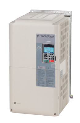
U1000


Рекуперативный матричный преобразователь частоты

Номинальные параметры  Класс 200 В, трехфазные: от 28 А до 248 А  Класс 400 В, трехфазные: от 11 А до 414 А

  • Энергосбережение в четырех квадрантах 
  • Автоматическая коррекция данных двигателя 
  • Высокоэффективное преобразование без промежуточного выпрямления 
  • Простой монтаж, минимальная потребность в обслуживании 
  • Обеспечение безопасности: SIL3, безопасное снятие момента 
  • ЭМС-фильтр, низкий уровень гармоник входного тока (THDi < 5 %), рекуперативный преобразователь и преобразователь частоты — два в одном 
  • Дополнительные интерфейсы: EtherCAT, EtherNet/IP, PROFINET, DeviceNet, PROFIBUS-DP, Modbus TCP/IP, CANopen, MECHATROLINK-II и POWERLINK 
  • CE, UL, cUL и TÜV

Ordering information
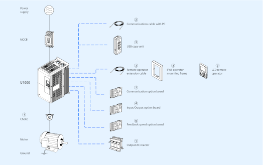
Note: U1000 includes EMC filter, input AC reactor, regenerative converter and frequency inverter.

U1000 inverter

Specifications

Order code

Voltage

Heavy duty

Normal duty

U1000

IP20/Nema1 kit

Input current

Rated output current

Input current

Rated output current

200 V

20 A

22 A

25 A

28 A

CIMR-UC2E0028AAA

EZZ022745A

25 A

28 A

38 A

42 A

CIMR-UC2E0042AAA

EZZ022745B

38 A

42 A

49 A

54 A

CIMR-UC2E0054AAA

49 A

54 A

62 A

68 A

CIMR-UC2E0068AAA

62 A

68 A

74 A

81 A

CIMR-UC2E0081AAA

74 A

81 A

95 A

104 A

CIMR-UC2E0104AAA

EZZ022745C

95 A

104 A

118 A

130 A

CIMR-UC2E0130AAA

118 A

130 A

140 A

154 A

CIMR-UC2E0154AAA

EZZ022745D

140 A

154 A

175 A

192 A

CIMR-UC2E0192AAA

175 A

192 A

226 A

248 A

CIMR-UC2E0248AAA

EZZ022745E

400 V

8.7 A

9.6 A

10 A

11 A

CIMR-UC4E0011AAA

EZZ022745A

10 A

11 A

13 A

14 A

CIMR-UC4E0014AAA

13 A

14 A

19 A

21 A

CIMR-UC4E0021AAA

19 A

21 A

25 A

27 A

CIMR-UC4E0027AAA

25 A

27 A

31 A

34 A

CIMR-UC4E0034AAA

31 A

34 A

36 A

40 A

CIMR-UC4E0040AAA

EZZ022745B

36 A

40 A

47 A

52 A

CIMR-UC4E0052AAA

47 A

52 A

59 A

65 A

CIMR-UC4E0065AAA

59 A

65 A

70 A

77 A

CIMR-UC4E0077AAA

70 A

77 A

87 A

96 A

CIMR-UC4E0096AAA

EZZ022745C

87 A

96 A

113 A

124 A

CIMR-UC4E0124AAA

113 A

124 A

142 A

156 A

CIMR-UC4E0156AAA

EZZ022745D

142 A

156 A

164 A

180 A

CIMR-UC4E0180AAA

164 A

180 A

197 A

216 A

CIMR-UC4E0216AAA

EZZ022745E

197 A

216 A

218 A

240 A

CIMR-UC4E0240AAA

218 A

240 A

275 A

302 A

CIMR-UC4E0302AAA

EZZ022745F

275 A

302 A

329 A

361 A

CIMR-UC4E0361AAA

329 A

361 A

377 A

414 A

CIMR-UC4E0414AAA

Note: The U1000 model has an IP00 protection class. For the IP20 protection class, install the IP20/Nema1 kit.

Output AC reactor

3-phase 200 VAC

3-phase 400 VAC

Model

Output AC reactor

Model

Output AC reactor

CIMR-UC2E0028AAA

AX-RAO01150220-DE

CIMR-UC4E0011AAA

AX-RAO04600110-DE

CIMR-UC2E0042AAA

AX-RAO00950320-DE

CIMR-UC4E0014AAA

CIMR-UC2E0054AAA

AX-RAO00630430-DE

CIMR-UC4E0021AAA

AX-RAO03600160-DE

CIMR-UC2E0068AAA

AX-RAO00490640-DE

CIMR-UC4E0027AAA

AX-RAO02500220-DE

CIMR-UC2E0081AAA

AX-RAO00390800-DE

CIMR-UC4E0034AAA

AX-RAO02000320-DE

CIMR-UC2E0104AAA

AX-RAO00330950-DE

CIMR-UC4E0040AAA

AX-RAO01650400-DE

CIMR-UC2E0130AAA

AX-RAO00251210-DE

CIMR-UC4E0052AAA

CIMR-UC2E0154AAA

AX-RAO00191450-DE

CIMR-UC4E0065AAA

AX-RAO01030580-DE

CIMR-UC2E0192AAA

AX-RAO00161820-DE

CIMR-UC4E0077AAA

AX-RAO00800750-DE

CIMR-UC2E0248AAA

AX-RAO00132200-DE

CIMR-UC4E0096AAA

AX-RAO00680900-DE


CIMR-UC4E0124AAA

AX-RAO00531100-DE

CIMR-UC4E0156AAA

AX-RAO00401490-DE

CIMR-UC4E0180AAA

AX-RAO00331760-DE

CIMR-UC4E0216AAA

AX-RAO00262170-DE

CIMR-UC4E0240AAA

CIMR-UC4E0302AAA

AX-RAO00212600-DE

CIMR-UC4E0361AAA

-

CIMR-UC4E0414AAA

Note: This table corresponds with HD rating. When ND is used, please choose the reactor for the next size inverter.

Choke

Diameter

Description

Order code

21

For 2.2 kW motors or below

AX-FER2102-RE

25

For 15 kW motors or below

AX-FER2515-RE

50

For 45 kW motors or below

AX-FER5045-RE

60

For 55 kW motors or above

AX-FER6055-RE

Communication option board

Description

Function

Order code

CANopen

Used for running or stopping the inverter, setting or referencing parameters, and monitoring output frequency, output current, or similar items through CANopen communication with the host controller.

SI-S3

DeviceNet

Used for running or stopping the inverter, setting or referencing parameters, and monitoring output frequency, output current, or similar items through DeviceNet communication with the host controller.

SI-N3

EtherCAT

Used for running or stopping the inverter, setting or referencing parameters, and monitoring output frequency, output current, or similar items through EtherCAT communication with the host controller.

SI-ES3

EtherNet/IP

Used for running or stopping the inverter, setting or referencing parameters, and monitoring output frequency, output current, or similar items through EtherNet/IP communication with the host controller.

SI-EN3

MECHATROLINK-II

Used for running or stopping the inverter, setting or referencing parameters, and monitoring output frequency, output current, or similar items through MECHATROLINK-II communication with the host controller.

SI-T3

Modbus TCP/IP

Used for running or stopping the inverter, setting or referencing parameters, and monitoring output frequency, output current, or similar items through Modbus TCP/IP communication with the host controller.

SI-EM3

POWERLINK

Used for running or stopping the inverter, setting or referencing parameters, and monitoring output frequency, output current, or similar items through POWERLINK communication with the host controller.

SI-EL3

PROFIBUS-DP

Used for running or stopping the inverter, setting or referencing parameters, and monitoring output frequency, output current, or similar items through PROFIBUS-DP communication with the host controller.

SI-P3

PROFINET

Used for running or stopping the inverter, setting or referencing parameters, and monitoring output frequency, output current, or similar items through PROFINET communication with the host controller.

SI-EP3

Accessories

Type

Description

Function

Order code

Digital operator

Remote operator extension cable

3 meters cable for connecting remote operator

3G3AX-CAJOP300-EE

IP65 operator mounting frame

Provides a simple way of installing the LCD

remote operator of the inverter on a cabinet

wall or door

JVOP-V11001

LCD remote operator

LCD display operator with language support

JVOP-180

LED operator

5-digits LED operator with copy function

JVOP-182

Accessories

USB copy unit

USB converter for PC tool usage and copy unit for easy parameter setup duplication and backup in one

JVOP-181

Input/Output option board

Description

Function

Order code

Analog input

Allows high precision, high resolution analog reference input.

Input channels: 3

Voltage input: -10 to 10 VDC (20 kΩ), 13-bit signed

Current input: 4 to 20 mA or 0 to 20 mA (250 Ω), 12-bit

AI-A3

Analog monitor

Provides extra multi-function analog output terminals.

Output channels: 2

Output voltage: -10 to 10 VDC, 11-bit (signed)

AO-A3

Digital input

Used to set the frequency reference by digital inputs.

Input channels: 18 (including SET and SIGN signals)

Input signal type: BCD 16-bit (4 digit), 12-bit (3 digit), 8-bit (2 digit)

Input signal: 24 VDC, 8 mA

DI-A3

Digital output

Provides extra insulated multi-function digital outputs.

Photocoupler relays: 6 (48 V, up to 50 mA)

Contact relays: 2 (250 VAC/30 VDC, up to 1 A)

DO-A3

Feedback speed option board

Description

Function

Order code

Motor PG feedback open collector

interface

For speed feedback input by connecting a motor encoder.

Input: 3 track (one or two tracks), for HTL encoder connection, 50 KHz max.

Output: 3 track, open collector.

Encoder power supply: 12 V, 200 mA max.

PG-B3

Motor PG feedback line driver interface

For speed feedback input by connecting a motor encoder.

Input: 3 track (one or two tracks), line driver, 300 KHz max.

Output: 3 track, line driver.

Encoder power supply: 5 or 12 V, 200 mA max.

PG-X3

Motor feedback resolver interface

For motor speed feedback by connecting a resolver (TS2640N321E64 by Tamagawa Seiki Co., LTD)

Input voltage: 7 VAC rms, 10 KHz

Transformation ratio: 0.5 ±5%

Maximum input current: 100 mA rms

PG-RT3

Specifications

200 V class

Three-phase: CIMR-UC2E_

0028

0042

0054

0068

0081

0104

0130

0154

0192

0248

In/Out characteristics

Input current at HD1

A

20

25

38

49

62

74

95

118

140

175

Input current at ND1

A

25

38

49

62

74

95

118

140

175

226

Rated input capacity at HD2

kVA

9

12

17

22

28

34

43

54

64

80

Rated input capacity at ND2

kVA

12

17

22

28

34

43

54

64

80

103

Rated output current at HD3

A

22

28

42

54

68

81

104

130

154

192

Rated output current at ND3

A

28

42

54

68

81

104

130

154

192

248

Overload tolerance

%

HD rating: 150% of rated output current for 60 s

ND rating: 120% of rated output current for 60 s

(Derating may be required for applications that start and stop frequently)

Output voltage

V

0 to Mains supply voltage

Carrier frequency4

Hz

4 KHz (user adjustable up to 10 KHz. Derating may be required)

Max. output frequency

Hz

400 Hz5

Power
supply

Rated input voltage and frequency

Three-phase 200 to 240 VAC, 50/60 Hz

Allowable voltage fluctuation

-15% to +10%

Allowable frequency fluctuation

±3% (frequency fluctuation rate: 1 Hz/100 ms or less)

Harmonics current distortion, THDI6

< 5% (IEEE519 compliant)

Input power factor6

0.98 min (during rated operation)

Efficiency

> 96%

Weight with IP00 protection

kg

21

33

36

63

115

181

Weight with IP20 protection

kg

22.5

35

38

65

118

185

400 V class

Three-phase: CIMR-UC4E_

0011

0014

0021

0027

0034

0040

0052

0065

0077

0096

0124

0156

0180

0216

0240

0302

0361

0414

In/Out characteristics

Input current at HD7

A

8.7

10

13

19

25

31

36

47

59

70

87

113

142

164

197

218

275

329

Input current at ND1

A

10

13

19

25

31

36

47

59

70

87

113

142

164

197

218

275

329

377

Rated input capacity at HD8

kVA

8

9

12

17

22

28

33

43

54

64

80

103

130

150

180

200

251

300

Rated input capacity at ND2

kVA

9

12

17

22

28

33

43

54

64

80

103

130

150

180

200

251

300

344

Rated output current at HD9

A

9.6

11

14

21

27

34

40

52

65

77

96

124

156

180

216

240

302

361

Rated output current at ND3

A

11

14

21

27

34

40

52

65

77

96

124

156

180

216

240

302

361

414

Overload tolerance

%

HD rating: 150% of rated output current for 60 s

ND rating: 120% of rated output current for 60 s

(Derating may be required for applications that start and stop frequently)

Output voltage

V

0 to Mains supply voltage

Carrier frequency10

Hz

4 KHz (user adjustable up to 10 KHz. Derating may be required)

Max. output frequency

Hz

400 Hz11

Power
supply

Rated input voltage and frequency

Three-phase 380 to 480 VAC, 50/60 Hz

Allowable voltage fluctuation

-15% to +10%

Allowable frequency fluctuation

±3% (frequency fluctuation rate: 1 Hz/100 ms or less)

Harmonics current distortion, THDI12

< 5% (IEEE519 compliant)

Input power factor6

0.98 min (during rated operation)

Efficiency

> 96%

Weight with IP00 protection

kg

21

33

36

63

115

181

267

Weight with IP20 protection

kg

22.5

35

38

65

118

185

278

Dimensions

Voltage class

Protection class

U1000 model

IP20/Nema1 kit model

Dimensions in mm


H

W

D

Weight (kg)

200 V

IP00

CIMR-UC2E0028AAA

-

480

250

360

21


CIMR-UC2E0042AAA

650

264

420

33

CIMR-UC2E0054AAA

CIMR-UC2E0068AAA

36

CIMR-UC2E0081AAA

CIMR-UC2E0104AAA

816

450

63

CIMR-UC2E0130AAA

CIMR-UC2E0154AAA

990

415

403

115

CIMR-UC2E0192AAA

CIMR-UC2E0248AAA

1,132

490

450

181

IP20/Nema113

CIMR-UC2E0028AAA

EZZ022745A

524

250

360

22.5

CIMR-UC2E0042AAA

EZZ022745B

705

264

420

35

CIMR-UC2E0054AAA

CIMR-UC2E0068AAA

38

CIMR-UC2E0081AAA

CIMR-UC2E0104AAA

EZZ022745C

885

450

65

CIMR-UC2E0130AAA

CIMR-UC2E0154AAA

EZZ022745D

1,107

415

403

118

CIMR-UC2E0192AAA

CIMR-UC2E0248AAA

EZZ022745E

1,320

490

450

185

400 V

IP00

CIMR-UC4E0011AAA

-

480

250

360

21

CIMR-UC4E0014AAA

CIMR-UC4E0021AAA

CIMR-UC4E0027AAA

CIMR-UC4E0034AAA

CIMR-UC4E0040AAA

650

264

420

33

CIMR-UC4E0052AAA

CIMR-UC4E0065AAA

36

CIMR-UC4E0077AAA

CIMR-UC4E0096AAA

816

450

63

CIMR-UC4E0124AAA

CIMR-UC4E0156AAA

990

415

403

115

CIMR-UC4E0180AAA

CIMR-UC4E0216AAA

1,132

490

450

181

CIMR-UC4E0240AAA

CIMR-UC4E0302AAA

695

267

CIMR-UC4E0361AAA

CIMR-UC4E0414AAA

IP20/Nema11

CIMR-UC4E0011AAA

EZZ022745A

524

250

360

22.5

CIMR-UC4E0014AAA

CIMR-UC4E0021AAA

CIMR-UC4E0027AAA

CIMR-UC4E0034AAA

CIMR-UC4E0040AAA

EZZ022745B

705

264

420

35

CIMR-UC4E0052AAA

CIMR-UC4E0065AAA

38

CIMR-UC4E0077AAA

CIMR-UC4E0096AAA

EZZ022745C

885

450

65

CIMR-UC4E0124AAA

CIMR-UC4E0156AAA

EZZ022745D

1,107

415

403

118

CIMR-UC4E0180AAA

CIMR-UC4E0216AAA

EZZ022745E

1,320

490

450

185

CIMR-UC4E0240AAA

CIMR-UC4E0302AAA

EZZ022745F

1,460

695

278

CIMR-UC4E0361AAA

CIMR-UC4E0414AAA


1. Assumes operation at the rated output current. Input current rating varies depending on the power supply transformer, input reactor, wiring connections and power supply impedance.

2. Rated input capacity is calculated with a power line voltage of 240 V × 1.1.

3. The rated output current of the drive output amps should be equal to or greater than the motor rated current.

4. Carrier frequency is set to 4 KHz. Current derating is required in order to raise the carrier frequency.

5. Adjustable by user.

6. If one of the following specifications are needed, the maximum output voltage will be the equivalent to the input voltage × 0.87: Harmonic current distortion of 5% or less, Harmonic suppression guidelines compliance or Input power factor of 0.98 or more.

7. Assumes operation at the rated output current. Input current rating varies depending on the power supply transformer, input reactor, wiring connections and power supply impedance.

8. Rated input capacity is calculated with a power line voltage of 480 V × 1.1.

9. The rated output current of the drive output amps should be equal to or greater than the motor rated current.

10. Carrier frequency is set to 4 KHz. Current derating is required in order to raise the carrier frequency.

11. Adjustable by user.

12. If one of the following specifications are needed, the maximum output voltage will be the equivalent to the input voltage × 0.87: Harmonic current distortion of 5% or less, Harmonic suppression guidelines compliance or Input power factor of 0.98 or more.

13. Dimensions and weight when the IP20/Nema1 kit is installed.

Regenerative accessories

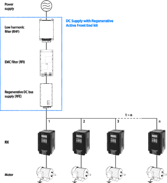
DC Supply with Regenerative Active Front End system
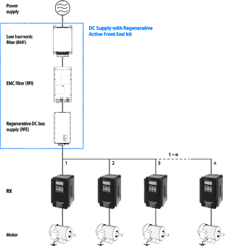
Regenerative DC bus supply

Reference: RFE-B3_

30

45

60

80

100

125

150

200

Max. input power kW

30

45

60

80

100

125

150

200

DC capacity μF

100

220

440

660

Max. input current A1

Driving

AC

65

98

130

173

217

271

325

433

DC

78

118

156

208

260

325

390

520

Braking

AC

52

78

104

139

173

217

260

346

DC

62

97

125

167

208

260

312

415

Rated input voltage

3-phase 400 V

Allowable voltage fluctuation

-15% to 10%

Mains frequency

40 to 60 Hz

Efficiency η

98%

Degree of protection

IP20

Ambient humidity

85% RH or less (without condensation)

Storage temperature

-25 to 55°C

Ambient temperature

5 to 40°C

Low harmonic filter

Reference: RHF-RA_

43

72

86

144

180

217

304

IRMS current A2

100% AC

43

72

86

144

180

217

304

150% AC

1 min in 10 min

64,5

108

129

216

270

325.5

456

Heat loss W1

242

352

374

488

692

743

905

Allowable voltage fluctuation

-15% to 10%

Power frequency

50 Hz

Efficiency η

98,5-99,5%

Degree of protection

IP20

Ambient humidity

85% RH or less (without condensation)

Storage temperature

-25 to 55°C

Ambient temperature

-20 to 45°C

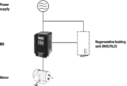
Regenerative Braking unit system

Regenerative Braking unit for Low Duty applications (50%)

Reference: RLD-E0_

8

12

16

20

24

32

40

48

58

80

95

116

140

170

200

Max. regenerative power kW

8

12

16

20

24

32

40

48

58

80

95

116

140

170

200

DC capacity μF

20

40

220

440

660

Max. current A3

DC

14

20

28

35

42

55

70

83

101

139

165

202

242

295

348

AC

12

17

23

29

35

46

58

69

84

116

137

168

202

246

290

Allowable voltage fluctuation

-15% to 10%

Mains frequency

50 to 60 Hz

Efficiency η

98%

Degree of protection

IP20

Ambient humidity

85% RH or less (without condensation)

Storage temperature

-25 to 55°C

Ambient temperature

5 to 40°C

Regenerative Braking unit for High Duty applications

Reference: RHD-B0_


7

13

18

24

30

50

70

100

125

150

Max. regenerative power kW

7

13

18

24

30

50

70

100

125

150

DC capacity μF

20

100

40

220

660

440

660

Max. current A4

DC I 100%

12

23

31

42

52

87

122

174

218

260

AC Ieff 100%

10

19

26

35

43

72

101

144

180

217

AC Ieff

60 s in 10 min

12

23

31

42

52

86

121

173

216

260

Allowable voltage fluctuation

-15% to 10%

Mains frequency

40 to 60 Hz

Efficiency η

98%

Degree of protection

IP20

Ambient humidity

85% RH or less (without condensation)

Storage temperature

-25 to 55°C

Ambient temperature

5 to 40°C


1. At nominal voltage 400 V. 1 min in 10 min.

2. At nominal voltage 400 V, 50 Hz.

3. At nominal voltage 400 V.

4. At nominal voltage 400 V.

1. At nominal voltage 400 V. 1 min in 10 min.

2. At nominal voltage 400 V, 50 Hz.

3. At nominal voltage 400 V.

4. At nominal voltage 400 V.