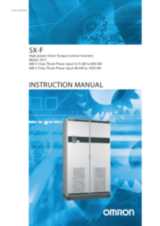
Ordering information
SX
| Specifications | Order code |
| Voltage | Heavy duty | Normal duty | IP54 model | IP20 model |
| Direct torque control | V/F | Direct torque control | V/F |
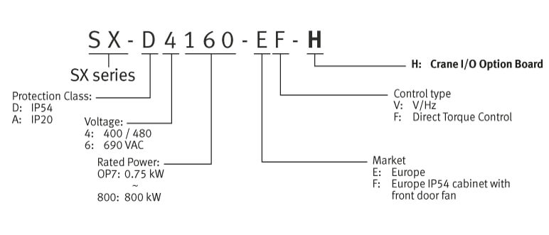
| 690 V | 75 kW | 72 A | 90 kW | 90 A | SX-D6090-EF | SX-D6090-EV | - | - |
| 90 kW | 87 A | 110 kW | 109 A | SX-D6110-EF | SX-D6110-EV |
| 110 kW | 117 A | 132 kW | 146 A | SX-D6132-EF | SX-D6132-EV |
| 132 kW | 140 A | 160 kW | 175 A | SX-D6160-EF | SX-D6160-EV |
| 160 kW | 160 A | 200 kW | 200 A | SX-D6200-E1F | SX-D6200-E1V |
| 200 kW | 200 A | 250 kW | 250 A | SX-D6250-E1F | SX-D6250-E1V | SX-A6250-EF | SX-A6250-EV |
| 250 kW | 240 A | 315 kW | 300 A | SX-D6315-E1F | SX-D6315-E1V | SX-A6315-EF | SX-A6315-EV |
| 315 kW | 300 A | 355 kW | 375 A | SX-D6355-E1F | SX-D6355-E1V | SX-A6355-EF | SX-A6355-EV |
| 315 kW | 344 A | 450 kW | 430 A | SX-D6450-E1F | SX-D6450-E1V | SX-A6450-EF | SX-A6450-EV |
| 355 kW | 400 A | 500 kW | 500 A | SX-D6500-E1F | SX-D6500-E1V | SX-A6500-EF | SX-A6500-EV |
| 450 kW | 480 A | 600 kW | 600 A | SX-D6600-E1F | SX-D6600-E1V | SX-A6600-EF | SX-A6600-EV |
| 500 kW | 520 A | 630 kW | 650 A | SX-D6630-E1F | SX-D6630-E1V | SX-A6630-EF | SX-A6630-EV |
| 600 kW | 576 A | 710 kW | 720 A | SX-D6710-E1F | SX-D6710-E1V | SX-A6710-EF | SX-A6710-EV |
| 650 kW | 640 A | 800 kW | 800 A | SX-D6800-E1F | SX-D6800-E1V | SX-A6800-EF | SX-A6800-EV |
| 710 kW | 720 A | 900 kW | 900 A | SX-D6900-E1F | SX-D6900-E1V | SX-A6900-EF | SX-A6900-EV |
| 800 kW | 800 A | 1,000 kW | 1,000 A | SX-D61K0-E1F | SX-D61K0-E1V | SX-A61K0-EF | SX-A61K0-EV |
A Panel kit
| Type | Description | Function | Order code |
| Panel kit | Panel kit | Complete panel kit including operator | SX-OP02-00-E |
| Blank panel kit | Complete panel kit including a blank operator | SX-OP02-01-E |
| Operator | Handheld control panel | Complete handheld control panel | SX-OPHH-00-E |
| Digital operator | Inverter digital operator | SX-OP01-00-E |
| Blank operator | Blank operator | SX-OP01-11-E |
② I/O option board
| Description | Function | Order code |
| Additional I/O option | Provides 3 extra relay outputs and 3 additional digital inputs | 01-3876-01 |
| Crane option | Dedicated option board for crane application, including additional I/O and functions | 01-3876-07 |
③ Communication option board
| Description | Function | Order code |
| RS232/485 | MODBUS RTU serial communication by RS232 or RS485 interface with galvanic isolation | 01-3876-04 |
| PROFIBUS-DP | Used for operating the inverter through PROFIBUS-DP communication with the host controller | 01-3876-05 |
| DeviceNet | Used for operating the inverter through DeviceNet communication with the host controller | 01-3876-06 |
| Modbus/TCP, Ethernet | Used for operating the inverter through Modbus/TCP communication with the host controller | 01-3876-09 |
| EtherCAT | Used for operating the inverter through EtherCAT communication with the host controller | 01-3876-10 |
| PROFINET (1-port) | Used for operating the inverter through PROFINET communication with the host controller | 01-3876-11 |
| PROFINET (2-ports) | 01-3876-12 |
④ Encoder feedback option card
| Description | Function | Order code |
| Encoder option | Used for connection of the actual motor speed via encoder. Up to 100 kHz with TTL and HTL incremental encoders with 5/24 V power supply | 01-3876-03 |
⑤ PTC/PT100 option card
| Description | Function | Order code |
| Thermal protection | Allows to connect a motor thermistor to the inverter | 01-3876-08 |
⑥ Braking chopper and braking resistor
All inverter sizes could be fitted with an optional built-in brake chopper from factory but is not possible to install it later. The choice of the resistor depends on the application switch-on duration and duty-cycle. Following tables describes the activation level of the built-in braking chopper and the minimum resistor that could be used depending on the input voltage.
| Rmin for different input voltage ( Ω) | Order code |
| 500-525 VAC | 550-600 VAC | 660-690 VAC |
| 4.9 | 5.7 | 6.5 | SX-D6090-EF |
| 4.9 | 5.7 | 6.5 | SX-D6110-EF |
| 4.9 | 5.7 | 6.5 | SX-D6132-EF |
| 4.9 | 5.7 | 6.5 | SX-D6160-EF |
| 2 × 4.9 | 2 × 5.7 | 2 × 6.5 | SX-D6200-EF |
| 2 × 4.9 | 2 × 5.7 | 2 × 6.5 | SX-D6250-EF |
| 2 × 4.9 | 2 × 5.7 | 2 × 6.5 | SX-D6315-EF |
| 2 × 4.9 | 2 × 5.7 | 2 × 6.5 | SX-D6355-EF |
| 3 × 4.9 | 3 × 5.7 | 3 × 5.7 | SX-D6450-EF |
| 3 × 4.9 | 3 × 5.7 | 3 × 5.7 | SX-D6500-EF |
| 4 × 4.9 | 4 × 5.7 | 4 × 5.7 | SX-D6600-EF |
| 4 × 4.9 | 4 × 5.7 | 4 × 5.7 | SX-D6630-EF |
| 6 × 4.9 | 6 × 5.7 | 6 × 5.7 | SX-D6710-EF |
| 6 × 4.9 | 6 × 5.7 | 6 × 5.7 | SX-D6800-EF |
| 6 × 4.9 | 6 × 5.7 | 6 × 5.7 | SX-D6900-EF |
| 6 × 4.9 | 6 × 5.7 | 6 × 5.7 | SX-D61K0-EF |
| Supply voltage (VAC) | Built-in brake chopper trigger level (VDC) |
| 500-525 | 860 |
| 550-600 | 1,000 |
| 660-690 | 1,150 |
⑦ Output coils
Output coils above SX-D4132-E should be order from factory as they should be installed inside of the cabinet
| Voltage | Inverter model | Rated current | Inductance | Rated voltage | Max carrier | Max. output frequency | Max. temp | Order code |
| 690 V | SX-D6090-EF | 90 A | 0.1 mH | 800 V | 6 kHz | 200 Hz | 40ºC | 473169 00 |
| SX-D6110-EF | 146 A | 0.05 mH | 6 kHz | 200 Hz | 473170 00 |
| SX-D6132-EF |
| SX-D6160-EF | 175 A | 0.05 mH | 6 kHz | 200 Hz | 473171 00 |
⑧ Overshoot clamp
Note: Only two types of overshoot clamps could be order for after mounting
| Inverter | Function | Order code |
| SX-6090 to SX-6160 | Together with the output coils, the overshoot clamp restricts the voltage and the dV/dt on the motor winding.
Inverters must be ordered including the option DC+/DC- connectors. | 52163 |
| SX-6200 to SX-61K0 | Together with the output coils, the overshoot clamp restricts the voltage and the dV/dt on the motor winding.
Doesn´t require the “DC+/DC-” option. | 52220 |
Computer software
| Installation | Order code |
| Configuration and monitoring software tool | CX-Drive |
| Configuration and monitoring software tool | CX-One |
| Software tool for energy saving calculation | €Saver |
Specifications
| Three-phase: SX-_6__-E_ | 90 | 110 | 132 | 160 | 200 | 250 | 315 | 355 | 450 | 500 | 600 | 630 | 710 | 800 | 900 | 1K0 |
| Motor
kW | For HD setting | 75 | 90 | 110 | 132 | 160 | 200 | 250 | 315 | 315 | 355 | 450 | 500 | 600 | 650 | 710 | 800 |
| For ND setting | 90 | 110 | 132 | 160 | 200 | 250 | 315 | 355 | 450 | 500 | 600 | 630 | 710 | 800 | 900 | 1,000 |
| Output
characteristics | Max output current (A) | 108 | 131 | 175 | 210 | 252 | 300 | 360 | 450 | 516 | 600 | 720 | 780 | 900 | 1,032 | 1,080 | 1,200 |
| Rated output current (A) at HD | 72 | 87 | 117 | 140 | 160 | 200 | 240 | 300 | 344 | 400 | 480 | 520 | 576 | 640 | 720 | 800 |
| Rated output current (A) at ND | 90 | 109 | 146 | 175 | 200 | 250 | 300 | 375 | 430 | 500 | 600 | 650 | 720 | 800 | 900 | 1,000 |
| Output voltage | 0 to Mains supply voltage |
| Max. output frequency | 400 Hz |
| Power
supply | Rated input voltage and frequency | 3-phase 500 to 690 V, 50/60 Hz |
| Allowable voltage fluctuation | 10% to -15% |
| Allowable frequency fluctuation | 45 to 65 Hz |
Dimensions
| Degree of protection | Drive model | H | W | D | |
| IP20 | SX-A6250 to SX-A6355 | 1,176 | 500 | 450 | |
| SX-A6450 to SX-A6600 | 1,176 | 730 | 450 |
| SX-A6630 to SX-A6800 | 1,176 | 1,100 | 450 |
| SX-A6900 to SX-A61K0 | 1,176 | 1,365 | 450 |
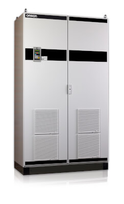
| IP54 | SX-D6090 to SX-D6200 | 952.5 | 344.5 | 314 |
| SX-D6250 to SX-D6355 | 2,250 | 600 | 600 |
| SX-D6450 to SX-D6600 | 2,250 | 900 | 600 |
| SX-D6630 to SX-D6800 | 2,250 | 1,200 | 600 |
| SX-D6900 to SX-D61K0 | 2,250 | 1,500 | 600 |
