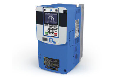
Q2A
Качественное регулирование - привод Q2A соответствует требованиям распространенных применений
- Управление в разомкнутом и замкнутом контуре или управление крутящим моментом
- Встроенные функции безопасности (STO SIL3)
- Встроенный фильтр ЭMC класса C3
- Соответствие требованиям стандартов EN 60721-3-3, 3S2 и 3C2
- Встроенный тормозной транзистор (до 90 кВт)
- Быстрая и простая настройка с помощью интуитивно понятной клавиатуры и навигации
- Карта памяти Micro SD для хранения данных
- Внутренние часы
- Вход питания 24 В пост. тока для платы управления
- Подключение: EtherCAT, EtherNet/IP, PROFINET, Modbus TCP/IP, POWERLINK
- Подключение мобильного устройства (через USB или Bluetooth)
- Рекуперативные решения в качестве дополнения
- CE, UL, cUL, EAC, RoHS
Improved motor performance
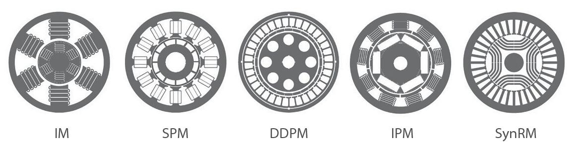
- Q2A позволяет управлять различными типами двигателей в разомкнутых и замкнутых контурах.
- Стандартные варианты с частотой до 590 Гц.
- Регулирование вплоть до нулевой скорости без энкодера.
- Минимум усилий по настройке со специальным векторным управлением EZ.
- Точное управление асинхронными, синхронными реактивными двигателями, двигателями с постоянными магнитами.
Cost effective network integration
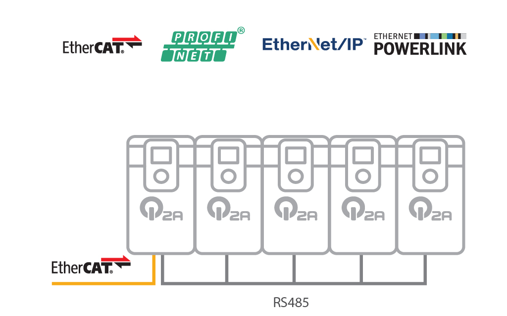
Подключение до пяти Q2A с одной дополнительной картой связи.
PC configuration tools: Q2edit and Q2dev
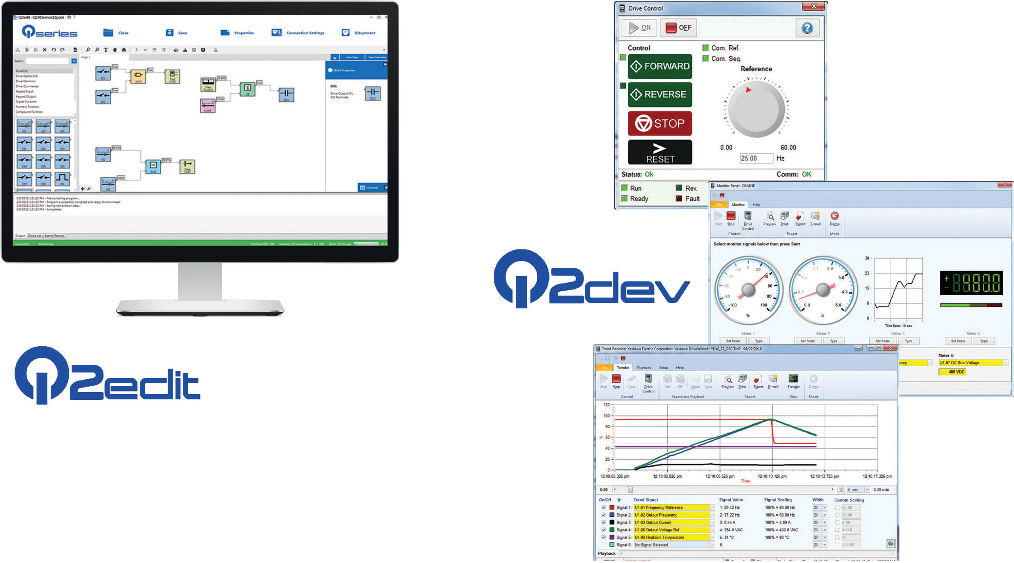
Оптимизируйте время проектирования. Графическая среда разработки позволяет быстрее настраивать индивидуальные конфигурации. Графические средства настройки: программа Q2edit обеспечивает возможность настройки параметров и мониторинга через компьютер.
Program >> Deploy >> Go
Приводы серии Q2A можно программировать без подключения источника питания. Просто подключите привод к одному из портов USB компьютера, начните программирование и оцените простоту ввода в эксплуатацию.
Ordering information
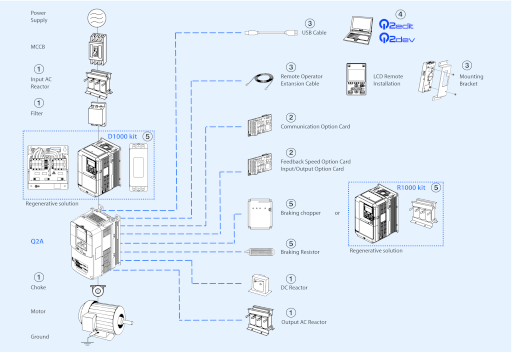
Q2A inverter
① Line filters
① Input AC reactors
① DC reactors
① Output AC reactors
Note: This table corresponds with HD rating. When ND is used, please choose the reactor for the next size inverter.
① Chokes
② Option cards
| Used for running or stopping the inverter, setting or referencing parameters, and monitoring output frequency, output current, or similar items through EtherCAT communication with the host controller. | |||
| Used for running or stopping the inverter, setting or referencing parameters, and monitoring output frequency, output current, or similar items through Modbus TCP/IP communication with the host controller. | |||
| Used for running or stopping the inverter, setting or referencing parameters, and monitoring output frequency, output current, or similar items through PROFINET communication with the host controller. | |||
| Used for running or stopping the inverter, setting or referencing parameters, and monitoring output frequency, output current, or similar items through EtherNet/IP communication with the host controller. | |||
| Used for running or stopping the inverter, setting or referencing parameters, and monitoring output frequency, output current, or similar items through POWERLINK communication with the host controller. | |||
| To configure very accurate analog references at high resolution | |||
| To use analog signals to monitor the drive output frequency and current | |||
| To use digital speed references and MFDI with a maximum 16 bits of resolution | |||
| To output insulated digital signals and monitor the operation status of the drive (alarm signals and detecting zero speed) | |||
| For speed feedback input by connecting a motor encoder | PG-B31 | ||
| For speed feedback input by connecting a motor encoder | PG-X32 | ||
| For speed feedback input by connecting a motor encoder | PG-F33 | ||
| For motor speed feedback by connecting a resolver (TS2640N321E64 by Tamagawa Seiki Co., LTD) | PG-RT34 |
③ Accessories
| This bracket is required to mount the LCD Remote Operator outside an enclosure panel | |||
④ Computer software
⑤ D1000 kit - DC Supply with Regenerative Active Front End
| Regenerative DC bus supply unit (D1000)5 | EMC filter1 | Low harmonic filter1 | ||
|---|---|---|---|---|
⑤ R1000 kit - Regenerative Braking unit
| Regenerative braking unit (R1000)6 | Current suppression reactor (1%)1 | ||
|---|---|---|---|
⑤ Braking unit, braking resistor unit
Specifications
400 V class
| < 460 V 1 | ||||||||||||||||
| ≥ 460 V 2 | ||||||||||||||||
| < 460 V 3 | ||||||||||||||||
| ≥ 460 V 4 | ||||||||||||||||
| Overload tolerance5 | ||||||||||||||||
| Carrier frequency6 | ||||||||||||||||
| < 460 V7 | |||||||||||||||
| ≥ 460 V8 | |||||||||||||||
| < 460 V9 | |||||||||||||||
| ≥ 460 V10 | |||||||||||||||
| Overload tolerance11 | |||||||||||||||
| Carrier frequency12 | |||||||||||||||
Dimensions
 | |||||
Note: For more detailed information about dimensions, please refer to the “I175E” datasheet.