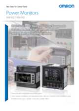
KM-N3
Универсальное устройство контроля мощности для монтажа в панель
- Удобное решение, простое в монтаже и применении
- Одно устройство может контролировать до четырех электрических цепей
- Поддерживаются трансформаторы тока общего назначения и электросети различного типа
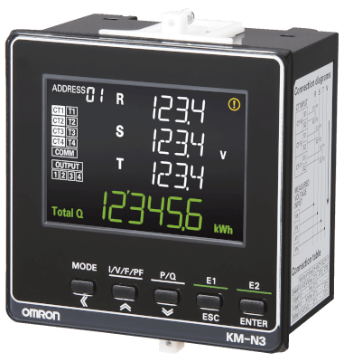
- ЖК-дисплей с крупными, хорошо видимыми цифрами белого и зеленого цвета
- Высокая точность измерений (класс 0.5S по IEC) (только устройство контроля мощности)
Ordering Information
Power monitor
Note: To use a commercially available current transformer, use a CT with a secondary current rating of 1 A or 5 A, and a rated load of at least 1.0 VA.
Optional products
| To be ordered separately. The cover improves protection of terminals | ||

Connectable OMRON split-type Current Transformers (CTs)
Note: The CT cables connected to the CT have the following recommended characteristics:
- cross section 0.75 mm² = AWG18
- 2C (number of internal wires is two)
- 1 m long maximum.
The CT cables are not provided by Omron
Specifications
Ratings (Power monitor)
| Single-phase two-wire, single-phase three-wire, three-phase three-wire, and three-phase four-wire | ||
| Single-phase two-wire: 4 circuits max., Single-phase three-wire or three-phase three-wire: 2 circuits max., | ||
| Single-phase, 2-wire: 100 to 277 VAC Single-phase, 3-wire: 100 to 240 VAC (L-N) or 200 to 480 VAC (L-L) Three-phase, 3-wire: 173 to 480 VAC (L-L) Three-phase, 4-wire: 100 to 277 VAC (L-N) or 173 to 480 VAC (L-L) | ||
| General-purpose CT with a rated secondary current of 1 A or 5 A1 | ||
| Overvoltage category II, measurement category II, pollution degree 2 | ||
| Industrial electromagnetic environment (EN/IEC 61326-1 Table 2) | ||
Ratings (Connectable OMRON Split-type Current Transformers (CTs))
| 100 MΩ min. (at 500 VDC) (Between through hole and output lead) | |||
| −20 to 55 °C, 85% max. relative humidity (with no condensation) | |||
| −30 to 90 °C, 85% max. relative humidity (with no condensation) | |||
Performance (Power monitor)
| Total power consumption (active, regenerative, and reactive), power (active and reactive), current, voltage, power factor, and frequency | ||
| 0.5% (IEC 62053-22 class 0.5S 2 | ||
| 2% (IEC 62053-23 class 2) 1 | ||
| (1) Between all electrical circuits and the case: 20 MΩ min. (at 500 VDC) (2) Between all power supply and voltage inputs and all communications and pulse output terminals: 20 MΩ max. (at 500 VDC) | ||
| (1) Between all electrical circuits and the case: 1,400 VAC for 1 min (2) Between all voltage and current inputs and all communications and pulse output terminals: 2,200 VAC for 1 min | ||
| Single amplitude: 0.1 mm, Acceleration: 15 m/s2, Frequency: 10 to 150 Hz, 10 sweeps for 8 min each along three axes | ||
| 150 m/s², 3 times each in 6 directions (up/down, left/right, forward/backward) | ||
| Number of outputs: 4 (photoMOS relay outputs) Used for the total power consumption pulse output. | ||
| 50 mA at 40 VDC ON residual voltage: 1.5 V max. (for output current of 50 mA) OFF leakage current: 0.1 mA max. | ||
| Output unit: 1, 10, 100, 1k, 5k, 10k, 50k, or 100k (wh) Pulse ON time: 500 ms (Cannot be changed.) | ||
| Data length: 7 or 8 bits Stop bits: 1 or 2 bits Vertical parity: Even, odd, or none | ||
| Modbus: 99, CompoWay/F: 31 If you measure more than one circuit with one Power Monitor, the number of circuits is treated as the number of connected Power Monitors. | ||
| Instruction Manual and Compliance Sheet, Mounting adapter and waterproof packing | ||